Figures & data
Figure 1. MER rover and instruments (http://marsrover.nasa.gov/mission/spacecraft_surface_rover.html).
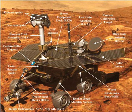
Figure 2. Curiosity and its instruments (NASA/JPL, http://mars.jpl.nasa.gov/msl/mission/instruments/).
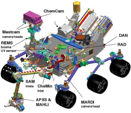
Table 1. Filters equipped on the two MSL Mastcams. Source: Modified from NASA/JPL (2012), http://msl-scicorner.jpl.nasa.gov/Instruments/Mastcam/.
Table 2. Parameters of the MSL Mastcams.
Table 3. Examples of sensors for Mars cartographic mapping on board Mars orbiters.
Figure 3. Key science targets at Gale crater shown on a CTX mosaic. The centre of the ellipse is 4.49 S, 137.42 E lat/lon. The ellipse is 20 × 25 km for scale. Images used in the mosaic are: B07_012195_1750_NS_05S222 W, B01_009927_1752_XN_04S222 W, and B21_017786_1746_SN_05S222 W.
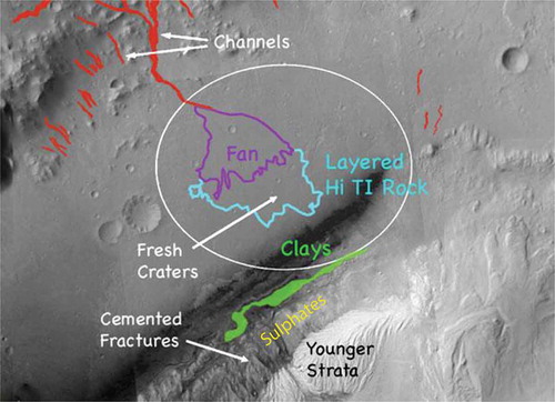
Figure 4. (a) Digital Elevation Model of the Gale crater region. (b) 3D view of strata exposed at the base of Mount Sharp, located in the centre of Gale crater. DEM constructed by USGS based on HiRISE images PSP_001488_1750 and PSP_001752_1750.
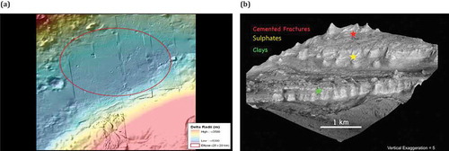
Figure 6. Anaglyph stereo HiRISE images: the MSL rover can be seen as a distinct object in HiRISE image (a), parachute and heat shield are found in (b) and (c).
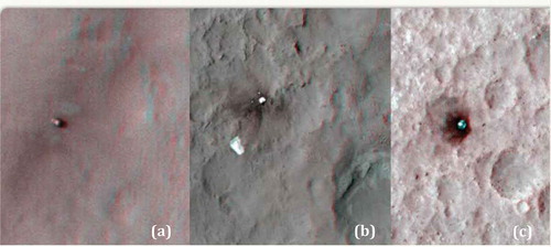
Figure 7. Two views of a sample trajectory correction by visual odometry.
Figure 8. Illustration of a rover traverse and the network with Pancam and Navcam images for bundle adjustment.
Figure 9. Vertical profile of the Spirit rover traverse (Sol 154 to Sol 670).
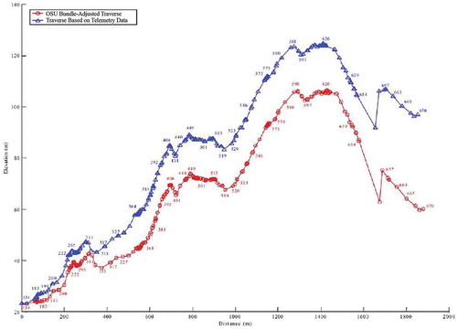
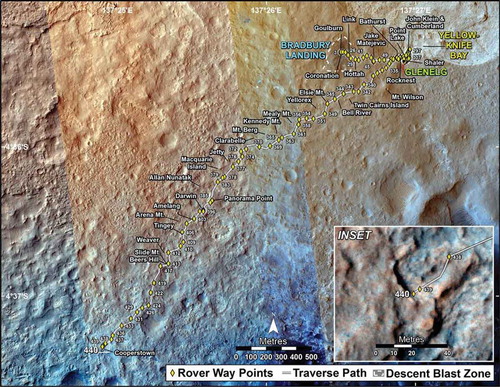
Figure 10. Curiosity traverse map (through Sol 440) (http:// mars.jpl.nasa.gov/msl/mission/timeline).