
Figures & data
Figure 1. Project geographic location.
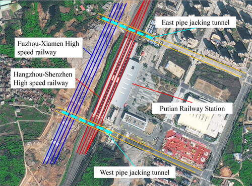
Figure 2. The Hangzhou-Shenzhen High-Speed Railway; (a) high-speed railway train; (b) tracks.

Figure 3. The Tianfei pipe-jacking machine.
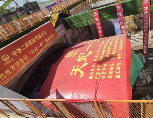
Table 1. Main parameters of the pipe jacking machine.
Figure 4. Detailed dimensions of segments.
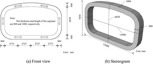
Figure 5. Geological conditions.
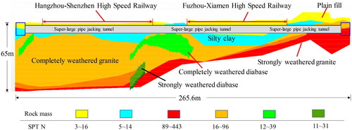
Figure 6. The composite stratum.
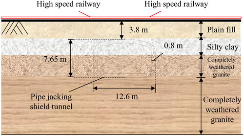
Figure 7. Refined numerical model.
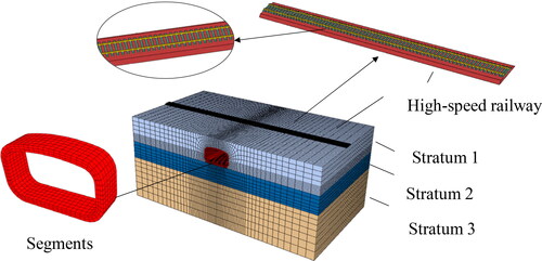
Figure 8. CDP parameters; (a) Cracking strain-damage parameter in tension; (b) Inelastic strain-damage parameter in compression; (c) Yield stress-crack strain curve in tension and(d) Yield stress-crack strain curve in tension in compression.
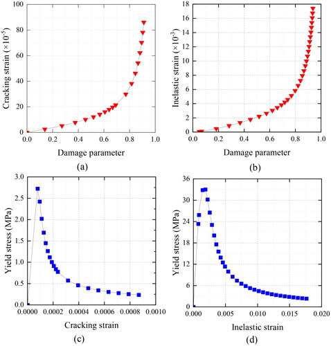
Table 2. Calculation parameters.
Figure 9. Arrangement of measuring points of displacement, stress, and safety factor.
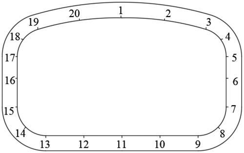
Figure 10. Schematic diagram of the composite stratum.
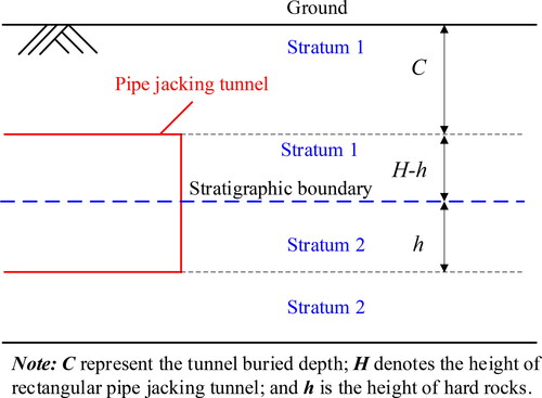
Figure 11. Track settlement of the high-speed railway.
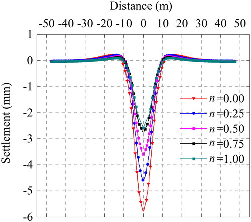
Figure 12. Segment convergence of the pipe jacking tunnel.
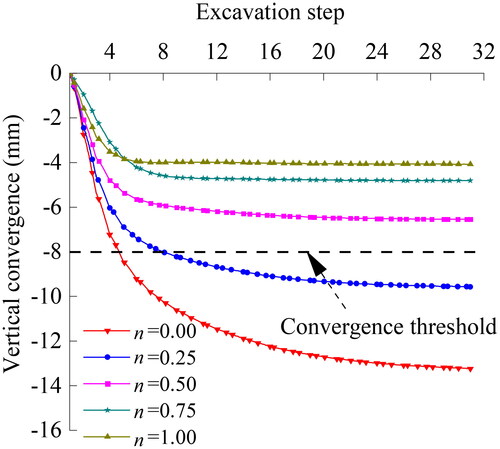
Figure 13. Minimum safety factor of the pipe-jacking tunnel.
Note: The circumferential and the radial number represent the measuring point (i.e., ) and the minimum safety factor, respectively
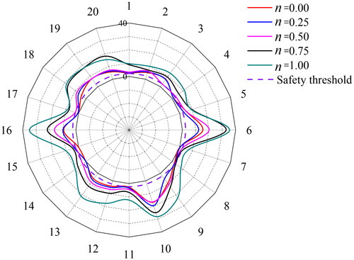
Figure 14. Risk factors of pipe-jacking construction under high-speed railway.
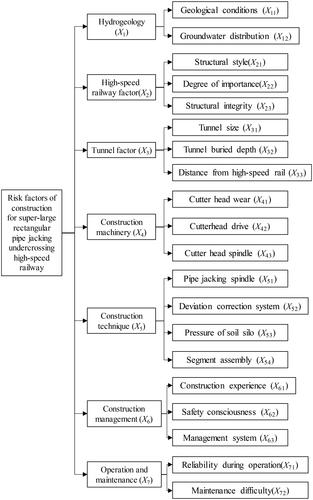
Table 3. Risk classification of super-large rectangular pipe jacking under high-speed railway.
Table 4. Risk level of pipe jacking under high-speed railway construction.
Table 5. Reinforcement schemes.
Figure 15. Numerical model of reinforcement schemes.
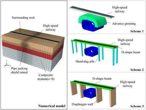
Figure 16. Stress nephogram of the reinforcement models; (a) Scheme 1; (b) Scheme 2; (c) Scheme 3.
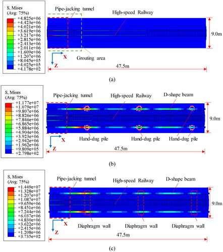
Figure 17. Track settlement of the high-speed railway.
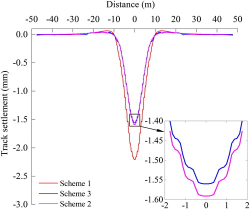
Table 6. Maximum of track settlement (Unit: mm).
Figure 18. Minimum safety factor of pipe jacking tunnel.
Note: The circumferential and the radial number represent the measuring point (i.e., ) and the minimum safety factor, respectively
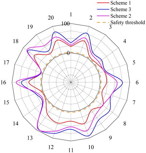
Table 7. Minimum of safety factor.
Table 8. Construction risk grade after reinforcement measures.
Figure 19. Reinforcement scheme of the Hangzhou-Shenzhen Railway.
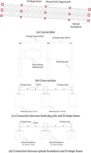
Figure 20. Site construction.
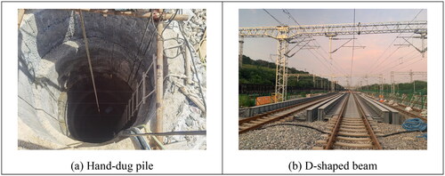
Figure 21. Construction scheme of pipe jacking tunnel crossing high-speed railway.
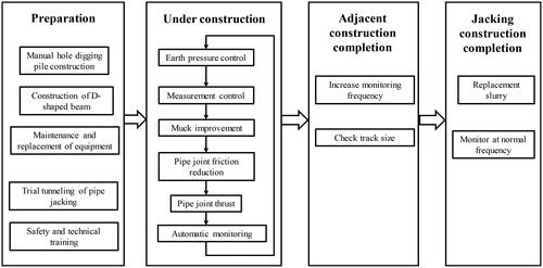
Figure 22. Monitoring equipment.
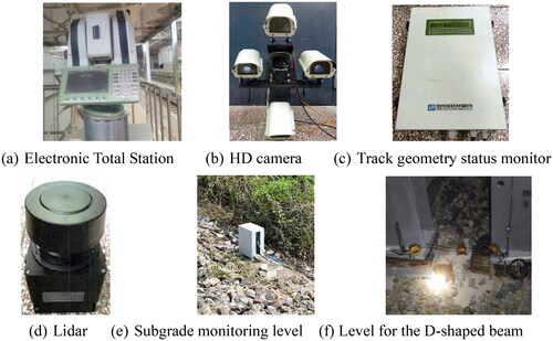
Figure 23. Track geometry monitoring system.
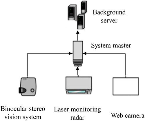
Table 9. Monitoring frequency.
Table 10. The double control value system.
Figure 24. Track settlement of high-speed railway.
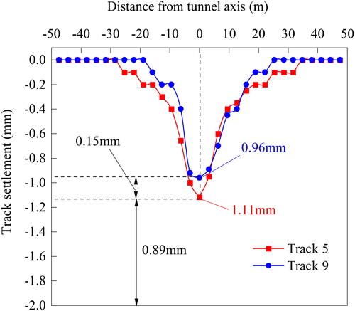
Table 11. Comparative analysis of the field investigation and numerical simulation.
Data availability statement
The authors confirm that the data supporting the findings of this study are available within the article.