
Figures & data
Figure 1. The location and the over view of the study area.
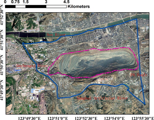
Figure 2. Zoning map of the drainage system.
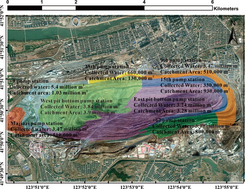
Figure 3. Comparison between outflow rate and precipitation.
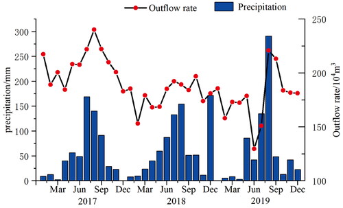
Figure 4. Model setup for the groundwater flow model. (a) hydrogeological units. (b) Overview of the mesh model.
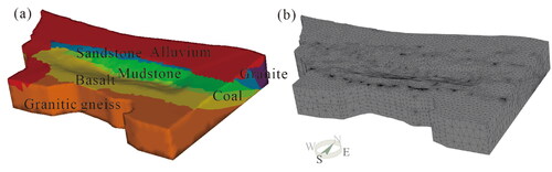
Figure 5. Water storage analysis module of the Fushun West Open-pit Mine WebGIS system.
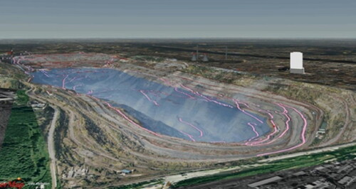
Figure 6. Schematic diagram of slope failure after water storage.
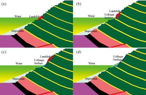
Table 1. Physical and mechanical parameters used in this study.
Figure 7. Simulation results. (a) Distribution of hydraulic head. (b) Degree of saturation. (c) Darcy flux. (d) Water table and hydraulic head of the E1000 profile.
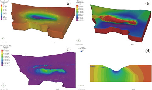
Table 2. Simulated rate budget of the actual open pit.
Figure 8. Pit Lake formation. (a) Inflow rate and cumulative volume with elevation. (b) Comparison of constant recharge rate and simulated water storage process.
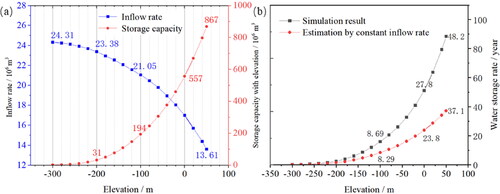
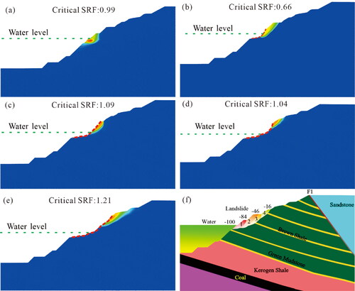
Figure 9. Evaluation of slope stability under water storage conditions. (a-d) Cumulative slope failures caused by water storage. (e) Stabilization of the slope with an critical SRF of 1.24. (f) Schematic diagram of the slope failure process and the affected area.
Data availability statement
The data that support the findings of this study are available from the corresponding authors, upon reasonable request.