2,918
Views
16
CrossRef citations to date
0
Altmetric
Original Articles

Application of computational fluid dynamics and surrogate-coupled evolutionary computing to enhance centrifugal-pump performance

, , , , &
Pages 171-181 | Received 20 Jun 2015, Accepted 02 Dec 2015, Published online: 20 Jan 2016

Figures & data

Figure 1. Optimization procedure.

Figure 1. Optimization procedure.

Table 1. Features of impeller.

Table 2. Meshing and boundary conditions.

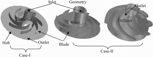
Figure 2. Geometry showing impeller, rotor and diffuser.

Figure 2. Geometry showing impeller, rotor and diffuser.

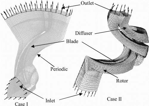
Figure 3. Mesh in flow domain for impeller, rotor and diffuser.

Figure 3. Mesh in flow domain for impeller, rotor and diffuser.

Table 3. Design variables with design space.

Figure 4. Case I PoF and cluster points for (a) different surrogates and (b) selected cluster points.
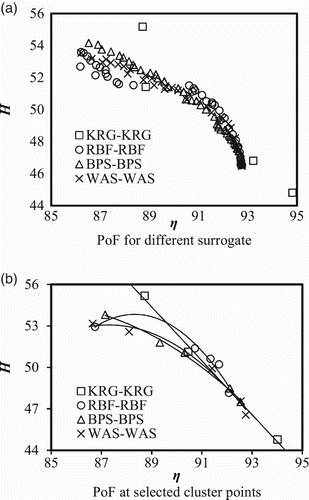
Figure 4. Case I PoF and cluster points for (a) different surrogates and (b) selected cluster points.

Table 4. PRESS for weights calculation.

Table 5. Surrogate-produced errors.

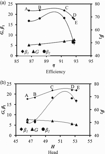
Figure 5. Case I design variables trend for WAS-WAS PoF (a) efficiency and (b) head.

Figure 5. Case I design variables trend for WAS-WAS PoF (a) efficiency and (b) head.

Table 6. Surrogate-produced errors for Case I.

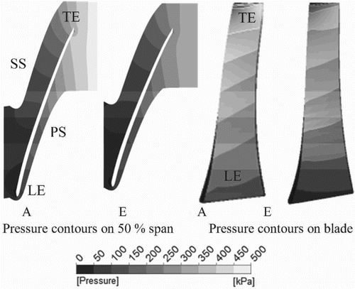
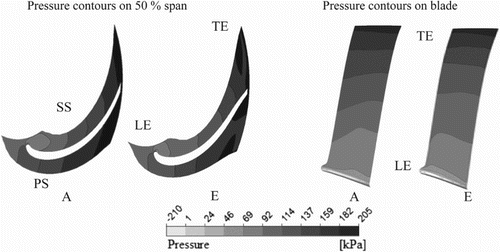
Figure 6. Case I pressure contours on pressure and suction side.

Figure 6. Case I pressure contours on pressure and suction side.

Figure 7. Case II PoF and cluster points for (a) different surrogates and (b) selected cluster points.
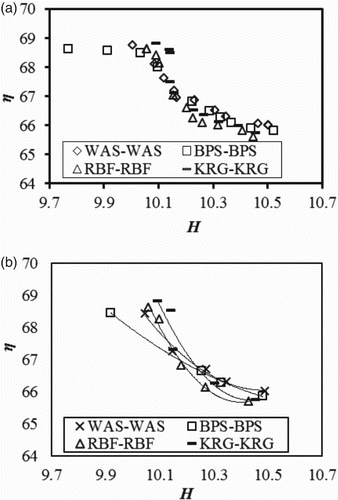
Figure 7. Case II PoF and cluster points for (a) different surrogates and (b) selected cluster points.
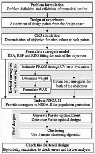
Figure 8. Case II design variables trend for WAS-WAS PoF (a) efficiency and (b) head.

Figure 8. Case II design variables trend for WAS-WAS PoF (a) efficiency and (b) head.

Table 7. Surrogate-produced errors for Case II.

Figure 9. Case II pressure distribution.

Figure 9. Case II pressure distribution.