1,836
Views
6
CrossRef citations to date
0
Altmetric
Original Articles

Numerical studies on fluid flow characteristics through different configurations of spiral casing

, &
Pages 296-310 | Received 30 Jun 2015, Accepted 27 Jan 2016, Published online: 29 Mar 2016

Figures & data

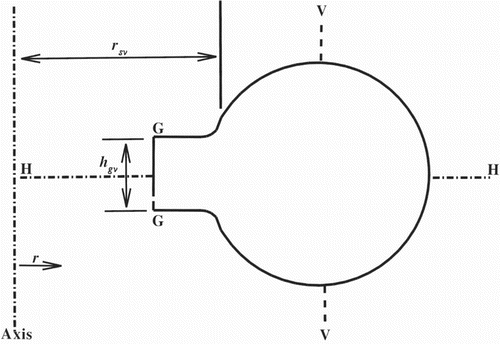
Figure 1. The computational domain with boundary conditions.

Figure 1. The computational domain with boundary conditions.

Figure 2. Comparison of the average radial velocity along the section VV for the accelerated type of spiral casing.
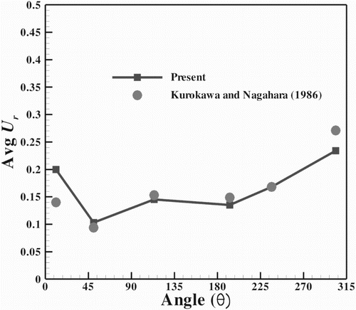
Figure 2. Comparison of the average radial velocity along the section VV for the accelerated type of spiral casing.

Figure 3. Comparison of (a) static pressure contours for (i) the present study and (ii) Maji and Biswas (Citation1999), and (b) the values at the cross-section for (i) the radial velocity and (ii) the tangential velocity.
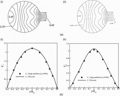
Figure 3. Comparison of (a) static pressure contours for (i) the present study and (ii) Maji and Biswas (Citation1999), and (b) the values at the cross-section for (i) the radial velocity and (ii) the tangential velocity.

Figure 4. Behavior of the secondary flow on the cross-stream planes of the decelerated type of spiral casing at (a) , (b) , (c) and (d) . Note: The length of the vector represents the magnitude of the velocity and the direction of the vector indicates the orientation of the flow.
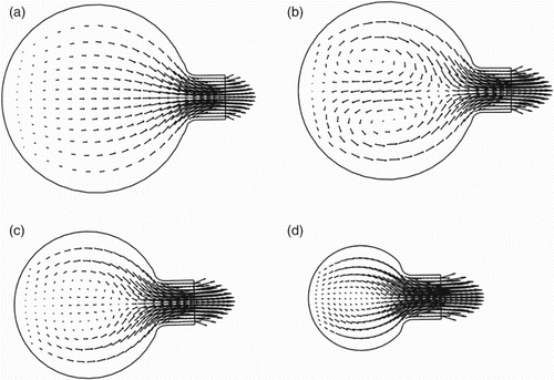
Figure 4. Behavior of the secondary flow on the cross-stream planes of the decelerated type of spiral casing at (a) , (b) , (c) and (d) . Note: The length of the vector represents the magnitude of the velocity and the direction of the vector indicates the orientation of the flow.

Figure 5. Zones on the cross-section of the spiral casing.

Figure 5. Zones on the cross-section of the spiral casing.

Figure 6. Distribution of (a) the static pressure, (b) the radial velocity and (c) the tangential velocity in section HH in different configurations of spiral casing for turn cross-sections at (i) and (ii) .
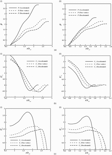
Figure 6. Distribution of (a) the static pressure, (b) the radial velocity and (c) the tangential velocity in section HH in different configurations of spiral casing for turn cross-sections at (i) and (ii) .

Figure 7. Distribution of (a) the static pressure, (b) the radial velocity and (c) the tangential velocity in section VV in different configurations of spiral casing for turn cross-sections at (i) and (ii) .
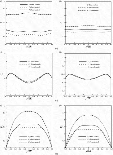
Figure 7. Distribution of (a) the static pressure, (b) the radial velocity and (c) the tangential velocity in section VV in different configurations of spiral casing for turn cross-sections at (i) and (ii) .

Figure 8. Distribution of (a) the radial velocity and (b) the tangential velocity in section GG in different configurations of spiral casing for turn cross-sections at (i) and (ii) .
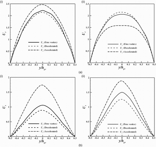
Figure 8. Distribution of (a) the radial velocity and (b) the tangential velocity in section GG in different configurations of spiral casing for turn cross-sections at (i) and (ii) .

Figure 9. Distribution of the average radial velocity in section GG in different configurations of spiral casing at different cross-sections.
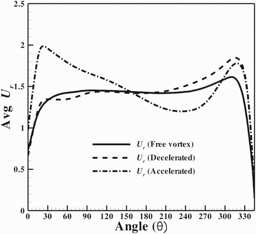
Figure 9. Distribution of the average radial velocity in section GG in different configurations of spiral casing at different cross-sections.

Figure 10. Distribution of (a) the static pressure, (b) the radial velocity and (c) the tangential velocity in section HH at the turn cross-section for various ARs in spiral casings of the type (i) decelerated, (ii) free vortex and (iii) accelerated.
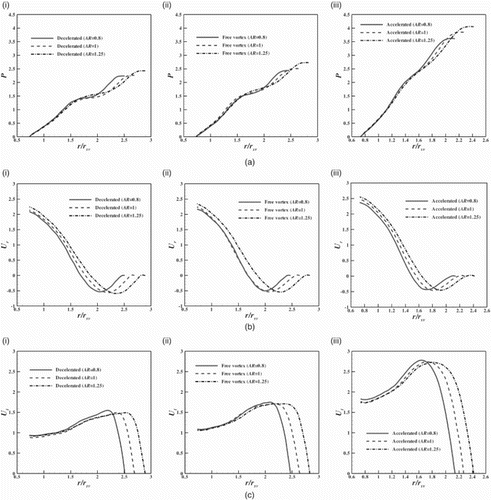
Figure 10. Distribution of (a) the static pressure, (b) the radial velocity and (c) the tangential velocity in section HH at the turn cross-section for various ARs in spiral casings of the type (i) decelerated, (ii) free vortex and (iii) accelerated.
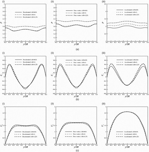
Figure 11. Distribution of (a) the static pressure, (b) the radial velocity and (c) the tangential velocity in section VV at the turn cross-section for various ARs in spiral casings of the type (i) decelerated, (ii) free vortex and (iii) accelerated.
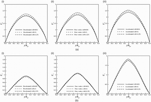
Figure 11. Distribution of (a) the static pressure, (b) the radial velocity and (c) the tangential velocity in section VV at the turn cross-section for various ARs in spiral casings of the type (i) decelerated, (ii) free vortex and (iii) accelerated.

Figure 12. Distribution of (a) the radial velocity and (b) the tangential velocity in section GG at the turn cross-section for various ARs in spiral casings of the type (i) decelerated, (ii) free vortex and (iii) accelerated.

Figure 12. Distribution of (a) the radial velocity and (b) the tangential velocity in section GG at the turn cross-section for various ARs in spiral casings of the type (i) decelerated, (ii) free vortex and (iii) accelerated.

Figure 13. Distribution of the average radial velocity in section GG for different ARs in various cross-sections in spiral casings of the type (a) decelerated, (b) free vortex and (c) accelerated.

Figure 13. Distribution of the average radial velocity in section GG for different ARs in various cross-sections in spiral casings of the type (a) decelerated, (b) free vortex and (c) accelerated.

Figure 14. Comparison of the average radial velocity in section GG for the free-vortex and decelerated types of spiral casing.
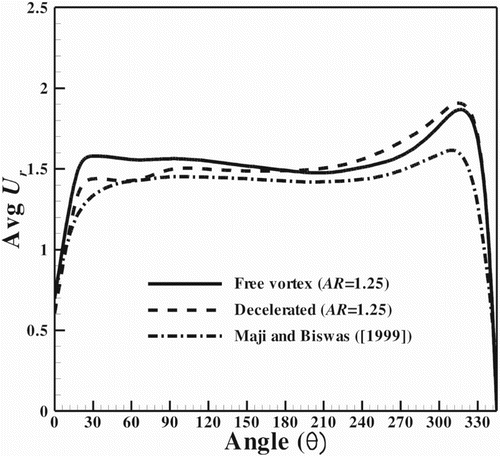
Figure 14. Comparison of the average radial velocity in section GG for the free-vortex and decelerated types of spiral casing.
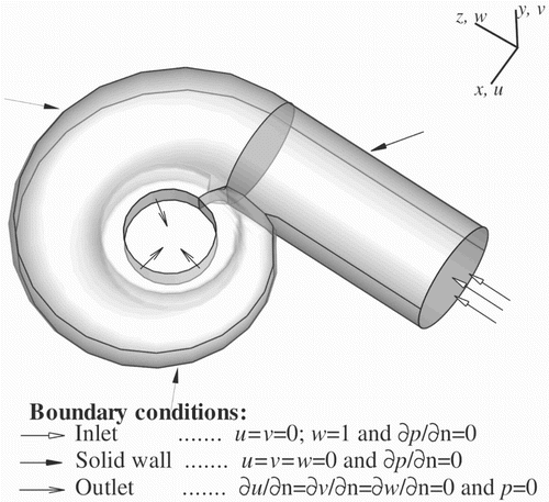
Table 1. Total pressure loss in different configurations of spiral casing with different ARs.

Table 2. Spiral velocity coefficients in different configurations of spiral casing with different ARs.