Figures & data
Figure 1. Description of a pipe overflow structure.
Figure 2. Different types of flow at the orifice.
Figure 3. Different types of flow in the pipe.
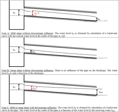
Figure 4. Description of the simulation domain.
Figure 5. Evolution of the free surface for the different cases by CFD.
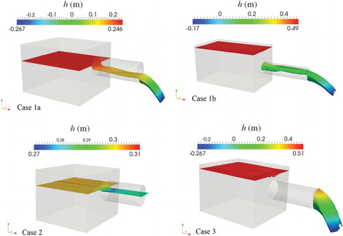
Table 1. Geometric and hydraulic characteristics of the studied configurations.
Figure 6. Evolution of the hydraulic head for a pipe with a diameter of 500 mm and a discharge of 84 l/s.
Figure 7. Comparison between numerical experiments and the US DoT (Citation2012) relationship for case 1a.
Figure 8. Evolution of the dimensionless discharge versus the upstream dimensionless water depth for free flows.
Figure 9. Evolution of versus
for submerged flows.
Figure 10. Flow chart for determining the type of flow as a function of the discharge and the water depths.
Figure 11. Dimensionless discharges versus dimensionless upstream water depth and .
Figure 12. Relationship between the discharge and the water level in the tank for free flow.
Figure 13. Limits between free flows and submerged flows.
Table 2. Verification of the submerged conditions at the orifice as a function of the water level upstream.
Figure 14. Relationship between the discharge and the water level in the tank for submerged flow.