Figures & data
Figure 1. Schematic diagram of the presented coupling method.
Figure 2. Flow chart of the coupled CFD/VWM method.
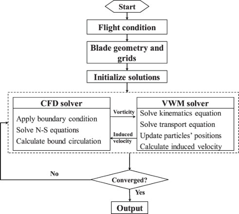
Figure 3. Predicted rotor-wake structure and wake-induced downwash for a rotor in forward flight: (a) rotor-wake geometry and (b) radial distribution of the wake-induced downwash.
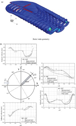
Figure 4. Time-varied wake-induced downwash at 0° azimuthal angle for (a) r = 0.74R and (b) r = 0.86R.
Figure 5. Effects of the computational parameters on the rotor-induced velocity for (a) the wake cut-off distance, (b) the overlap factor, and (c) the minimum vortex size.
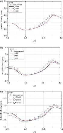
Figure 6. Overset grid system for the hover case: (a) C-O-type blade grid and (b) half-cylinder background mesh.
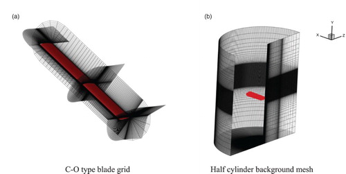
Figure 7. Predicted rotor-wake structure from the full CFD method (Caradonna–Tung rotor): (a) rotor-wake geometry () and (b) vorticity contour slice crossing the rotor center.
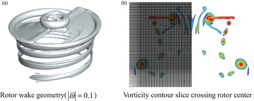
Figure 8. Computational domain of the coupling method for the hover case.
Figure 9. Predicted rotor-wake structure from the coupling method (Caradonna–Tung rotor in the hover case): (a) rotor-wake geometry () and (b) vorticity contour slice crossing the rotor center.
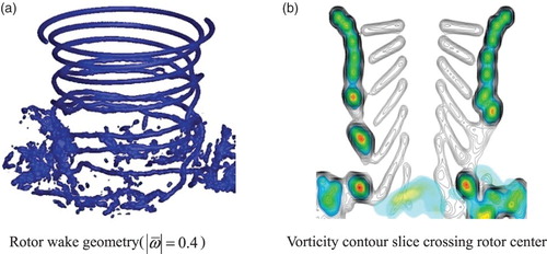
Figure 10. Predicted radial and axial displacements of the rotor tip vortex.
Figure 11. Close-up of the rotor tip vortex passing to the CFD domain.
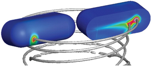
Figure 12. Chordwise pressure coefficient distribution on the blade surface (Caradonna–Tung rotor in the hover case) for: (a) r/R = 0.68, (b) r/R = 0.80, (c) r/R = 0.89, and (d) r/R = 0.96.
Figure 13. Sectional lift coefficient distribution along the blade span.
Table 1. Comparison of computation times between the coupling method and the full CFD method.
Figure 14. Computational domain for the coupling method in forward flight.
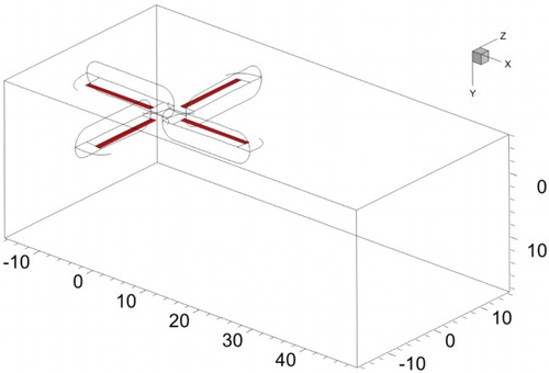
Figure 15. Predicted rotor-wake structure via the coupling method (7A rotor): (a) rotor-wake geometry and (b) vorticity contour slices.
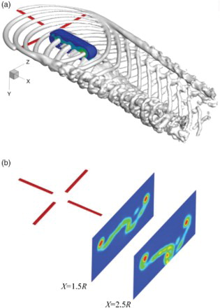
Figure 16. Overset grid system used for the forward flight case.
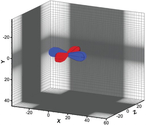
Figure 17. Rotor-wake structure predicted by the full CFD method (7A rotor): (a) rotor-wake geometry, (b) slice1, x = 1.5R, and (c) slice2, x = 2.5R.
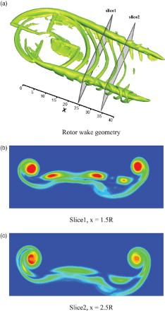
Figure 18. Vorticity contour on a vertical slice crossing the rotor center (7A rotor) for (a) the full CFD method and (b) the coupling method.
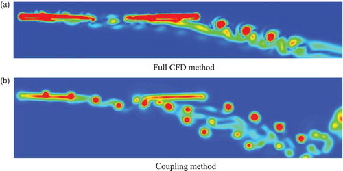
Figure 19. Chordwise pressure distribution on the blade surface at 0.82R (7A rotor) for: (a) , (b)
, (c)
, and (d)
Figure 20. Time history of sectional normal force coefficient for (a) r/R = 0.82 and (b) r/R = 0.92.
Figure 21. Sectional normal force coefficient (3/rev and higher) for (a) r/R = 0.5, (b) r/R = 0.70, c) r/R = 0.82, and (d) r/R = 0.92.
Table 2. Comparison of computation time between the coupling method and the full CFD method for the forward flight case.
Figure 22. Predicted rotor-wake structure using the coupling method (UH-60A rotor).
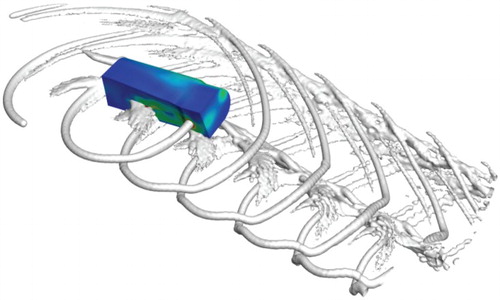
Figure 23. Chordwise pressure coefficient distribution at r/R = 0.775 (UH-60A rotor) for (a) , (b)
, (c)
, and (d)
.
Figure 24. Chordwise pressure coefficient distribution at r/R = 0.865 (UH-60A rotor) for (a) , (b)
, (c)
, and (d)
.
Figure 25. Section normal force coefficient (UH-60A rotor) for: (a) r/R = 0.775, (b) r/R = 0.865, (c) r/R = 0.920, and (d) r/R = 0.965.