Figures & data
Figure 1. The standard L-shaped housed viscous pump.
Figure 2. The alternative pump configurations: (a) enlarged inlet and (b) enlarged outlet.
Table 1. Validation of the numerical method.
Table 2. Validation of grid independence.
Figure 3. Pump performance with different Reynolds numbers: (a) dimensionless mass flow rate and (b) dimensionless driving power.
Figure 4. The experimental apparatus: (a) schematic diagram, (b) test rig, and (c) pump assembly schematic.
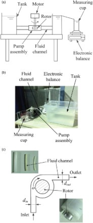
Figure 5. Measured flow rate (a) with a constant outlet area and (b) with a constant inlet area.
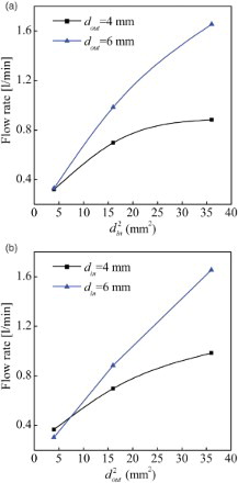
Figure 6. Pump performance under different pressure loads: (a) dimensionless mass flow rate and (b) dimensionless driving power.
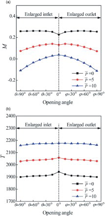
Figure 7. Impact of the Reynolds number on pump performance.
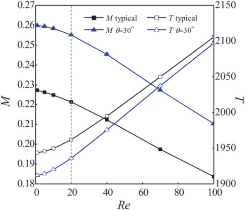
Figure 8. Impact of the pressure load on pump performance: (a) dimensionless mass flow rate and (b) dimensionless driving power.
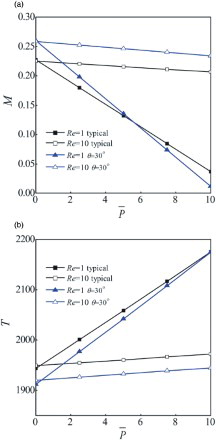
Figure 9. Streamlines for pumps with different inlet opening angles.
Figure 10. Flow patterns for the pump with θ = 30°.