1,980
Views
1
CrossRef citations to date
0
Altmetric
Articles

3D internal forced convection heat-transfer correlations from CFD for building performance simulation

&
Pages 553-566 | Received 16 Aug 2017, Accepted 11 May 2018, Published online: 26 Jun 2018

Figures & data

Figure 1. The geometric parameters of: (a) the 3D enclosure with inlet and outlet openings; (b) the vertical 2D plane; (c) the horizontal 2D plane.
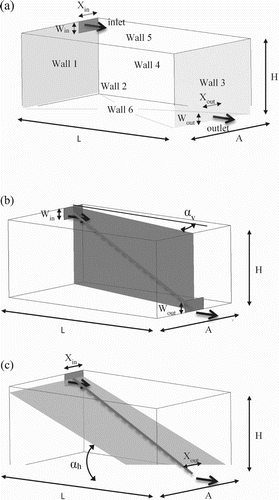
Figure 1. The geometric parameters of: (a) the 3D enclosure with inlet and outlet openings; (b) the vertical 2D plane; (c) the horizontal 2D plane.

Figure 2. The geometric parameters of: (a) the vertical 2D plane; (b) the horizontal 2D plane.

Figure 2. The geometric parameters of: (a) the vertical 2D plane; (b) the horizontal 2D plane.

Table 1. Boundary conditions of the vertical 2D, horizontal 2D, and 3D simulations.

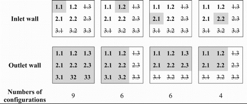
Figure 3. Symmetric and asymmetric configurations for the 3D model.

Figure 3. Symmetric and asymmetric configurations for the 3D model.

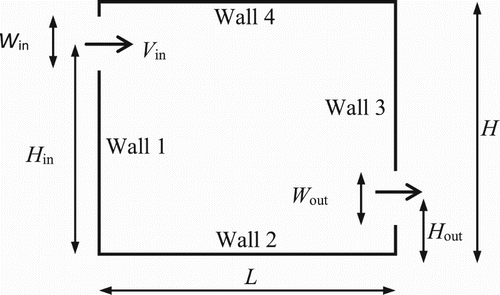
Figure 4. General geometric parameters for the 2D models.

Figure 4. General geometric parameters for the 2D models.

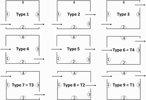
Figure 5. 2D configurations for different inlet and outlet opening positions.

Figure 5. 2D configurations for different inlet and outlet opening positions.

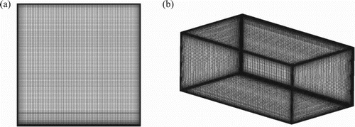
Figure 6. Uniform-growth mesh for: (a) a 2D model; (b) a 3D model.

Figure 6. Uniform-growth mesh for: (a) a 2D model; (b) a 3D model.

Figure 7. Grid sensitivity analysis for the 3D geometry case (where H = L = A = 3.00 m, Win = Wout = Xin = Xout = 0.42 m, Hin = 2.78 m, Ain = 0.22 m, Hout = 1.50 m, Aout = 1.50 m, Rein = 119,293, Twalls = 30°C, Tin = 10°C).
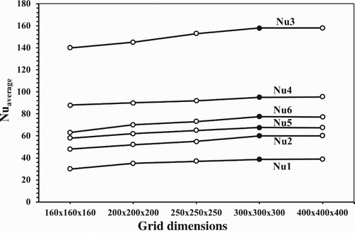
Figure 7. Grid sensitivity analysis for the 3D geometry case (where H = L = A = 3.00 m, Win = Wout = Xin = Xout = 0.42 m, Hin = 2.78 m, Ain = 0.22 m, Hout = 1.50 m, Aout = 1.50 m, Rein = 119,293, Twalls = 30°C, Tin = 10°C).

Table 2. 3D correlation coefficients according to the 2D planes.

Figure 8. Comparison of the correlated and simulated 3D Nu values for: (a) Walls 1 and 3; (b) Walls 2 and 4; (c) Walls 5 and 6.
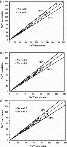
Figure 8. Comparison of the correlated and simulated 3D Nu values for: (a) Walls 1 and 3; (b) Walls 2 and 4; (c) Walls 5 and 6.

Table 3. Application range of the variables in the 2D models (dimensionless).

Figure 9. Comparison of the Nusselt numbers obtained by correlation and CFD simulation for: (a) Wall 1; (b) Wall 2; (c) Wall 3; (d) Wall 4.
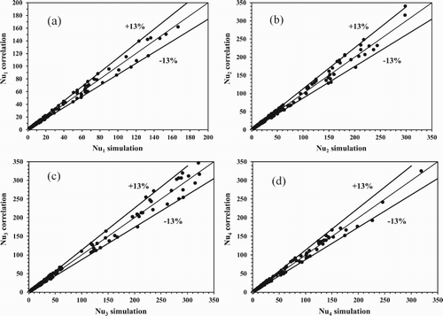
Figure 9. Comparison of the Nusselt numbers obtained by correlation and CFD simulation for: (a) Wall 1; (b) Wall 2; (c) Wall 3; (d) Wall 4.

Table 4. Correlation coefficients for the 2D models.

Figure 10. Test case for validating the methodology: (a) the vertical 2D plane; (b) the horizontal 2D plane.
Figure 10. Test case for validating the methodology: (a) the vertical 2D plane; (b) the horizontal 2D plane.

Table 5. Test case input parameters for the 3D and 2D models and the CHTCs for the six walls (h1 to h6) obtained by simulation and correlation.

Figure 11. Comparison of the CHTCs according to ACH with the correlations developed by other authors.
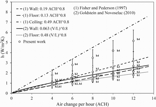
Figure 11. Comparison of the CHTCs according to ACH with the correlations developed by other authors.
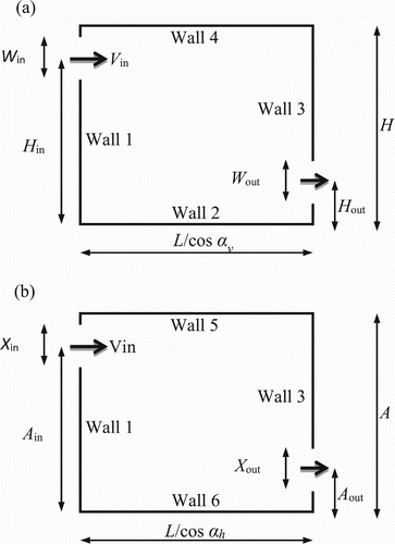
Table 6. Application range of the variables of the 3D models.