Figures & data
Figure 1. Existing and potential governance models for the main channel and beach areas in the lower Yellow River. (a) Existing ecological management strategy for the lower Yellow River by Zhang and Zhang (Citation2020); (b) An example of the systematic out-branching (Dragon style) river (from Google Earth Engine): Repartimento, Maués – State of Amazonas, Brazil (4°05′59.8″S 57°32′21.2″W); (c) The feasible Dragon-style river regulation pattern.
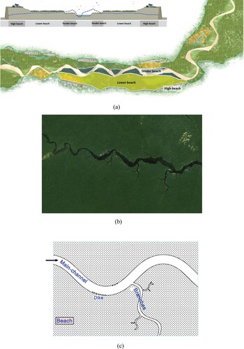
Figure 2. Simplified Dragon style river model and its design source. (a) Schematic diagram of the simplified channel bend model of Dragon style rivers; (b) Schematic view of our existing flume (through reducing flow speed, creating turbulence and vortices, inducing hydraulic jumps, and redirecting flow into less erosive paths, energy dissipater works to restrain the kinetic energy of flow).
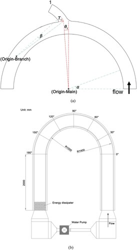
Table 1. Hydraulic parameters of the designed groups of simulation runs. Q is the inflow discharge, H is the mean water depth, B and B1 are the widths of the main-channel and the branch, R and R1 are the centreline radius of curvature of the main-channel and the branch, Fr is the inflow Froude number, θ1 and T1 are the two characteristic angles of the simplified channel model that indicate the relationships between the main-channel and the branch (see Figure (a)). The length of the branch channel is kept the same for all. Subruns-b are the group with the median parameters.
Figure 3. Horizontal and cross-sectional views of the mesh used in the simulations. (a) Horizontal sectional grids in the bend with single short branch; (b) Inlet and outlet sectional grids in main channel; (c) Branch outlet sectional grids.
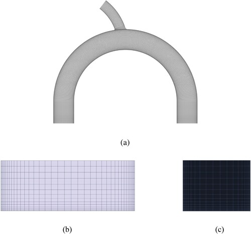

Figure 6. Velocity vectors of normalised time-averaged secondary flow (V/Uave) and contours of the time-averaged streamwise vorticity (ωs) at specific sections along the main-channel bend under the different branching conditions. Y = radial distance relative to the inner bank around the main-channel bend circle; Z = vertical distance relative to the bed. The unit of vorticity is 1/s. (a) B1/B approaching 0.7 under the branch-off situation; (b) R1/B approaching 3.5 under the branch-off situation; (c) θ1 approaching 2° from subrun-b under the branch-on situation.
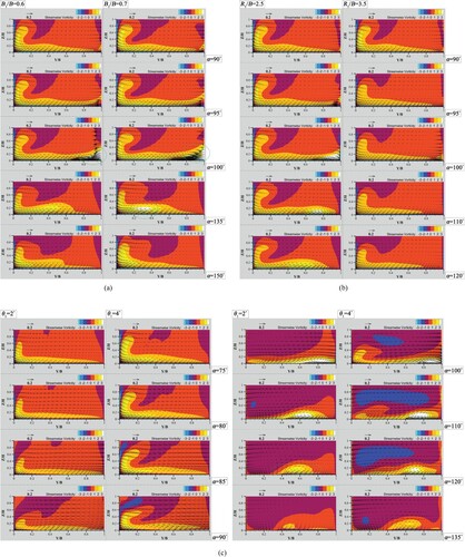

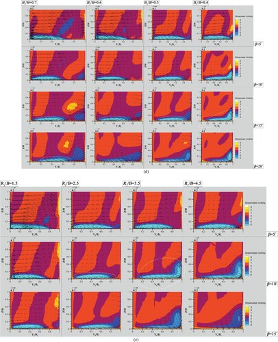


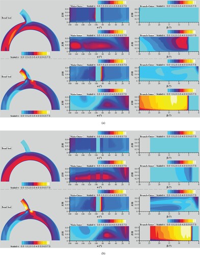
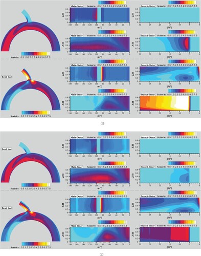
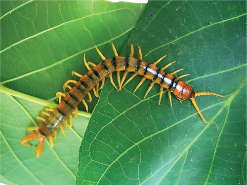
Figure 11. A sample image of typical arthropods – insects.