Figures & data
Figure 1. A PSP-841B propeller and definitions of the yaw angle Ψ, immersion ratio I = h/D, shaft inclination angle γ and PSP rate of revolution.
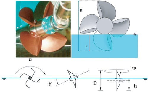
Figure 2. (a) The geometry of the PSP-841B (model and actual), and (b) values of teta (θ) for the various positions of the key blade.
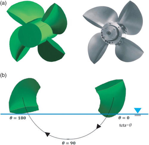
Table 1. Details of the PSP-841B propeller model.
Figure 3. The mesh generation around the PSP-841B propeller and computational domain for (a) the shaft and upstream, (b) the boundary layer on the cross-section of the propeller, (c) the structured mesh on the free surface, and (d) the outline of the domain, and (e) the computational domain and boundary conditions.
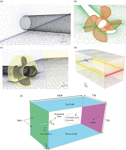
Table 2. Non-dimensional parameters of significance for ventilated propeller flows.
Table 3. Flow conditions for various advance coefficients.
Figure 4. Comparison between the calculated and measured KT, 10KQ.
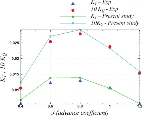
Figure 5. Comparison between the calculated and measured ηO.
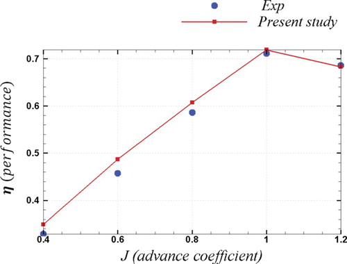
Figure 6. Relative percentage error versus advance coefficients.
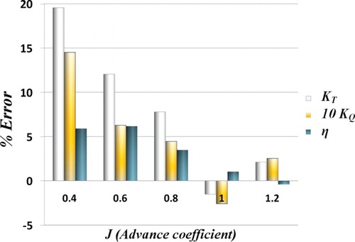
Figure 7. Comparison between the calculated and measured rotational fluctuation of the five-component force/moment versus the angular position of the key blade.
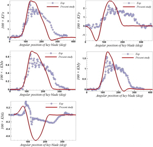
Figure 8. Comparison between the calculated and measured rotational fluctuation of the five-component force/moment versus the angular position of the key blade.
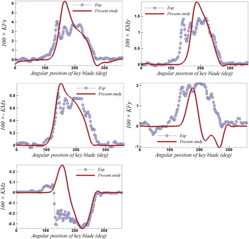
Figure 9. Comparison between the calculated and measured rotational fluctuation of the five-component force/moment versus the angular position of the key blade.
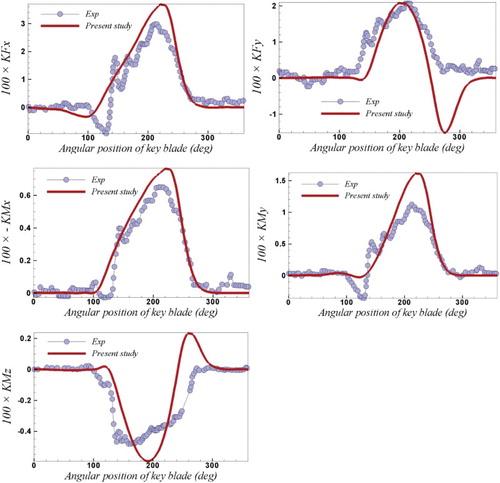
Figure 10. Comparison of the observed and simulated ventilation patterns.
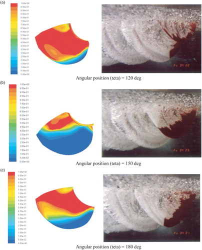
Figure 11. Contour of the total pressure on the face and back side of the PSP.
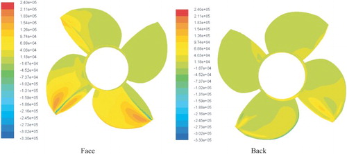
Figure 12. Contour of the total pressure on the face and back side of the PSP.
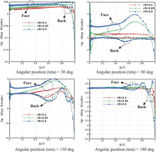
Figure 13. Contour of the ventilation pattern (VOF) on the cross-section of the PSP at different positions of propeller rotation.
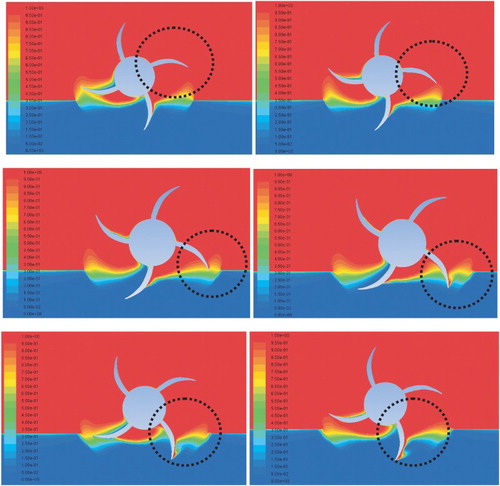
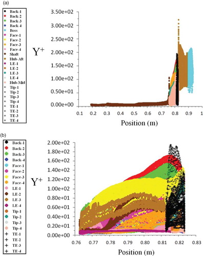
Figure 14. Graph of Y+ on (a) the shaft and propeller, and (b) the propeller.