Figures & data
Figure 1. The power triangle.
Figure 2. Simple circuit for reactive power theoretical analysis.
Figure 3. Operation limitations of generators.
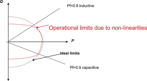
Figure 4. Extended electric load analysis, including P-balance, Q-balance and S-balance.
Figure 5. Selecting the appropriate generator out of G1 and G2, in order to meet the active and reactive power demands of electric balance analysis (denoted as *).
Table 1. Reactive power demands of certain electrical energy system components.
Figure 6. Schematic diagram of the potential locations of capacitors.
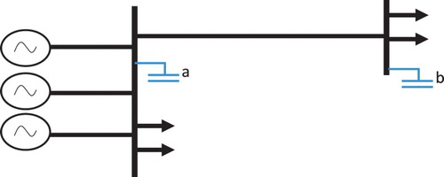
Figure 7. Harmonic spectrum of current with and without capacitor banks (case study from a power substation on the Hellenic Grid).
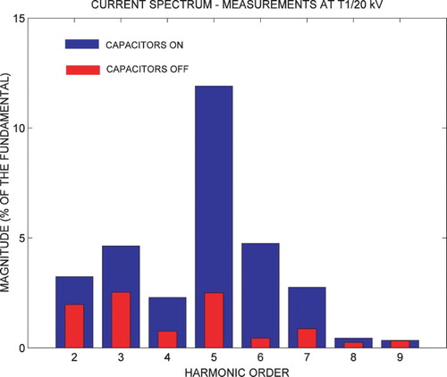
Figure 8. Transient overvoltage during the switching off of a capacitor bank (case study from a power substation on the Hellenic Grid).
Table 2. Reactive power analysis and pf (power factor) calculations for conventional propulsion.
Table 3. Reactive power analysis and pf calculations for diesel electric propulsion.
Figure 9. Feeding bus supplying M loads (k = 1, 2, … , M) without any reactive power source.
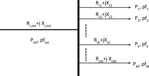
Figure 10. Feeding bus supplying M loads (k = 1, 2, … , M) with a reactive power source installed.
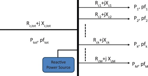
Figure 11. Voltage vs. reactive power curve of synchronous generators. (If the generator is forced to cover excessive reactive power demand, this could to the unstable region.) (Papadias Citation1985, Prousalidis Citation2005).
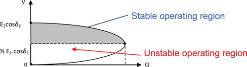
Figure 12. Simulation setup in the CitationMATLAB environment.
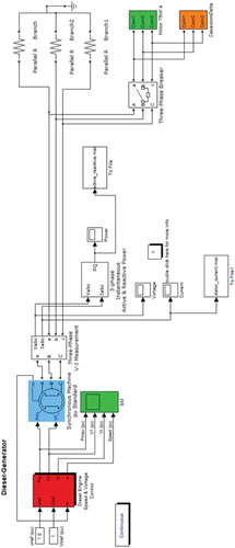
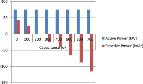
Figure 13. Energy demands in terms of active and reactive power from the system vs. reactive power capacitor.