
Figures & data
Figure 1. Bagging scheme for producing MI compaction barrier, (a) outer bag and (b) inner bag.
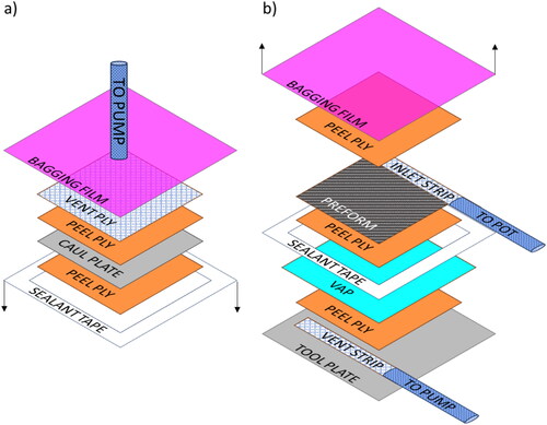
Figure 2. Compaction tooling (a) CAD model with front beam hidden and (b) actual set-up.
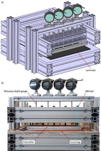
Figure 3. Set-up in XCT (a) photograph of installation on rotary stage and (b) schematic of vacuum flow.
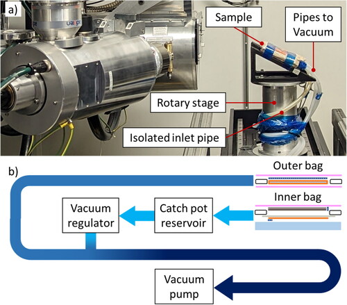
Figure 4. Sample midplane slices at given process steps (a) inner vacuum: 9.4mbar, outer vacuum: 1013mbar, (b) Inner vacuum: 9.4mbar, outer vacuum: 9.43mbar (c) Inner vacuum: 800mbar, outer vacuum: 9.4mbar, (d) Inner vacuum: 1013mbar, outer vacuum: 9.4mbar, (e) Inner vacuum: 9.4mbar, outer vacuum: 9.4mbar, (f) Inner vacuum: 9.4mbar, outer vacuum: 1013mbar.
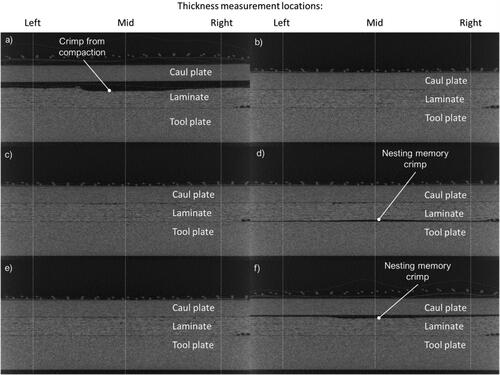
Table 1. Sample thickness and void volume measurements at given process steps.
Figure 5. Significant void volume transitions, (a) volume reference rendering, (b) initial state scan, (c) first notable void volume change, (d) large void pocket presented under the laminate, (e) void volume upon restoration of vacuum pressure, (f) void volume when caul p[late actuating outer bag vacuum is released.
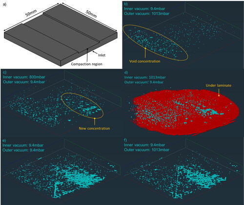
Figure 6. Flexural test parent panel, (a) non-optimized process C-scan, (b) optimized process C-scan, and (c) optimized process time of flight thickness analysis.
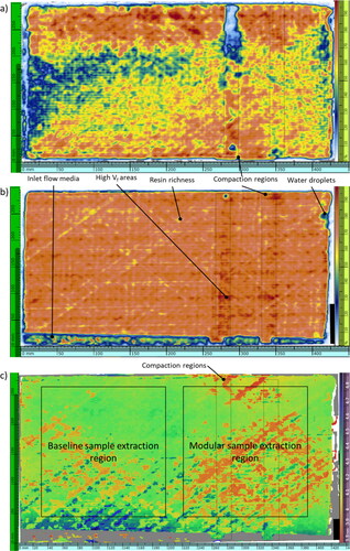
Figure 7. Time of flight thicknesses across the center of the optimized panel.
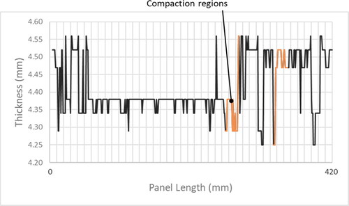
Table 2. Flexural test sample measurements.
Figure 8. Flexural test set-up.
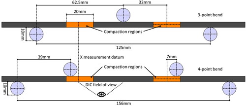
Figure 9. Three-point bend flexural strength results.
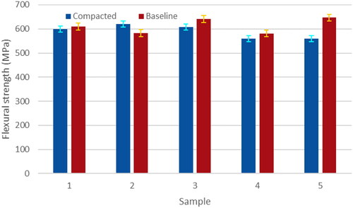
Figure 10. Four-point bend flexural strength results.
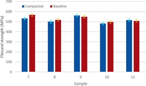
Figure 11. Three-point bend chord moduli.
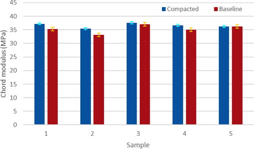
Figure 12. Four-point bend chord moduli.
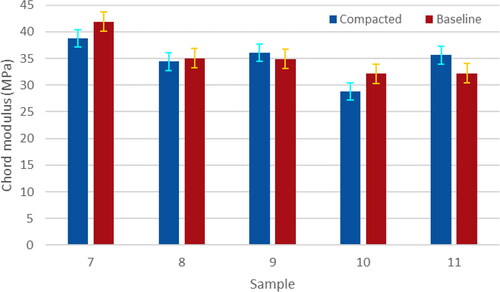
Figure 13. Three-point bend strain fields at 481 N loading (a) compacted example, (b) baseline example, (c) average strain and standard deviation at given position.
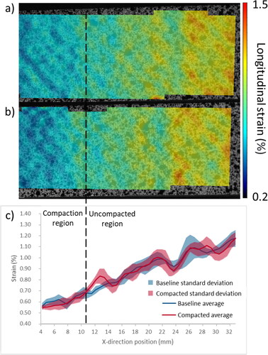
Figure 14. Four-point bend strain fields at 481 N loading (a) compacted example, (b) baseline example, (c) average strain and standard deviation at given position.
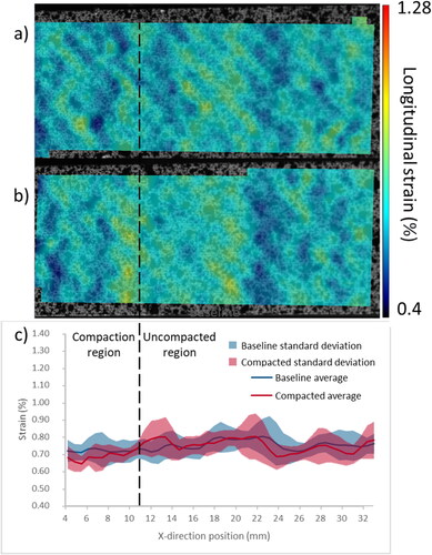
Table A1. XCT parameters and explanation of settings.
Table A2. DIC parameters.
Table A3. Three-point bend noise floor study.
Table A4. Four-point bend noise floor study.