Figures & data
Figure 1. Geometric dependency of the incidence radar beam: Local incidence angle (vertical) angle and azimuth (horizontal) angle
.
Table 1. Percentage frequency of the absolute value of the normalized backscatter difference over the area of Western Europe (). Original dataset and after azimuth-correction of the dataset (October 2014 – December 2016).
Figure 2. Normalized backscatter difference over Western Europe (October 2014 – December 2016).
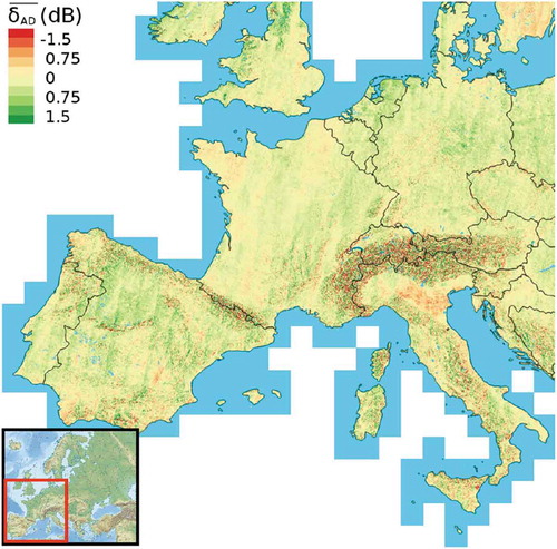
Figure 3. Austrian Alps: Backscatter shift due to different slope orientations: (a) Calculated from Sentinel-1 backscatter (equation (2)), and (b) modelled from SRTM-3 DEM using equation (4). (c),(d) Detail example of the Zillertal in the Tyrolean Alps.
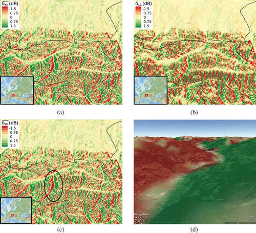
Figure 4. (a) Illustration of different azimuth angles for ascending and descending overpasses observing a predominant slope, and (b) modelled backscatter difference depending on the slope orientation
. (using equation (4), with
,
, s = 1).
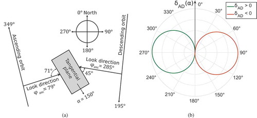
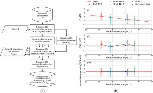
Figure 5. (a) Incidence and azimuth angle normalization workflow of the Sentinel-1 backscatter data, and (b) an example of the normalization steps: (i) 2 years of Sentinel-1 backscatter observed in VV-polarisation separated by orbit number, (ii) incidence angle normalized backscatter, and (iii) normalized and azimuth-corrected backscatter.