Figures & data
Figure 1. Ideal and practical single diode model of a PV cell.
Figure 2. Equivalent circuit of a PV module with series and parallel connected PV cells.
Figure 3. I−V and P−V characteristics of a solar cell.
Figure 4. Flowchart of PO MPPT method.
Figure 5. Flowchart of INC MPPT method.
Figure 6. INC MPPT with PI regulator.
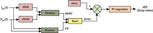
Figure 7. Fuzzy logic-based scheme for MPP tracking.
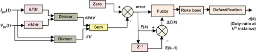
Figure 8. NN-based MPPT technique.
Figure 9. ANFIS-based MPPT scheme.
Figure 10. Block diagram of proposed control schemes for MPPT.
Figure 12. Structure of fuzzy tuner.
Figure 13. Response of fuzzy tuner for typical inputs.
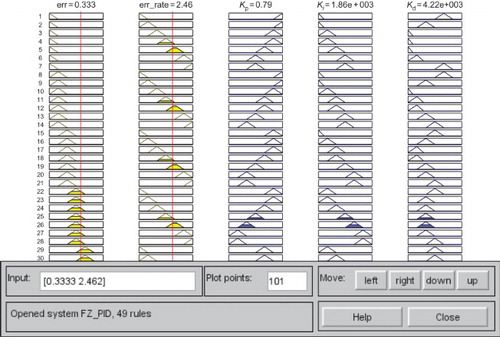
Table 1. Rule base for input and output membership functions.
Figure 14. (a) and (b) Configuration of asynchronous buck converter in solar PV system.
Table 2. Buck converter parameters.
Figure 15. Relay tuning method.
Table 3. PID parameters.
Table 4. PV module parameters at standard test conditions.
Figure 16. Hardware interfacing of using dSPACE™ R&D board.
Figure 17. Configuration of temperature sensor.
Figure 18. (a) Experimental set-up for real-time implementation of MPPT algorithms and (b) radiation and temperature sensors used for real-time simulations.
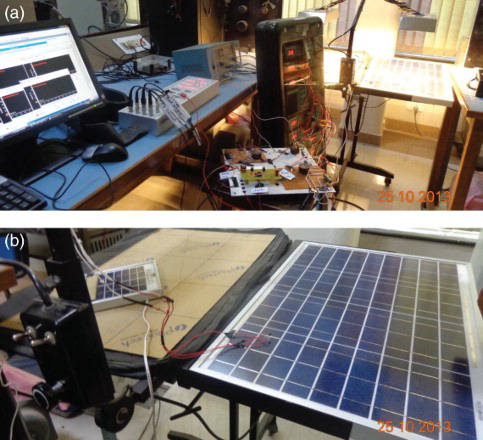
Figure 19. Subsystem for calculation of theoretical maximum power.
Figure 20. Model of the proposed MPPT controller.
Figure 21. Model for determination of PID parameters using relay method.
Figure 22. (a) Relay output and (b) process output.
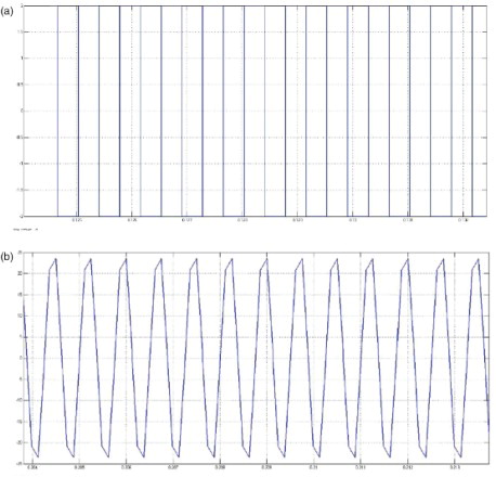
Figure 23. Model for PO MPPT controller.
Figure 24. Model of incremental conductance MPPT controller.
Figure 25. Model of fuzzy logic based MPPT controller.
Figure 26. Input output membership functions.
Table 5. Rule base for fuzzy MPPT system.
Figure 27. Model of neural network based MPPT controller.
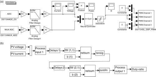
Table 6. MSE and regression values of training, validation and testing process.
Figure 28. Model of ANFIS based MPPT controller.
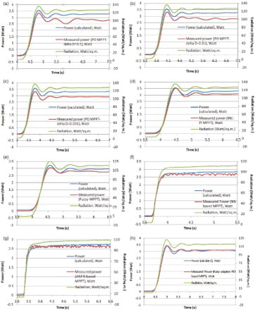
Figure 29. (a) Response of PO MPPT with Δ D=0.1, (b) response of PO MPPT with Δ D=0.01, (c) response of PO MPPT with Δ D=0.001, (d) response of INC with PI regulator (INC-PI) MPPT, (e) response of fuzzy logic-based MPPT, (f) response of NN-based MPPT, (g) response of ANFIS-based MPPT and (h) response of proposed fuzzy adaptive PID-based MPPT.