Figures & data
Figure 1. The actual USV.
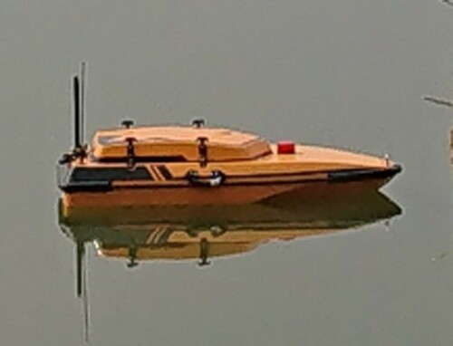
Figure 2. Plane movement diagram of USV, where ,
and
represent the forward speed, sway speed and yaw speed.
and
denote the course angle and rudder angle.
is resultant velocity of
and
.
is the attachment coordinate system, and
is the centre of gravity of the USV,
is the geodetic coordinate system, and
is the origin, and
represents the due north direction (Fossen, Citation1957).
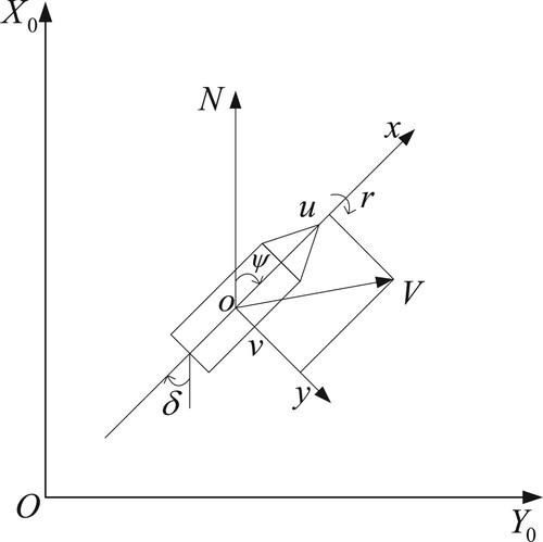
Figure 3. Principle of ADRC.
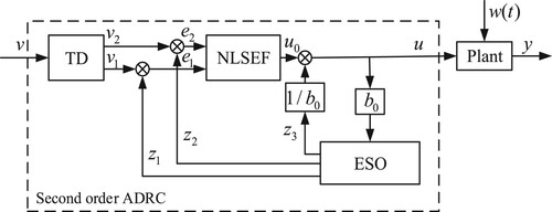
Figure 4. Firefly algorithm principle.
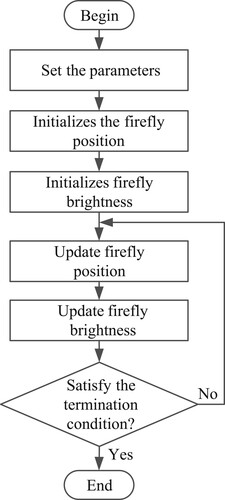
Figure 5. ADRC parameter setting based on FA, where is the system reference input,
is the control quantity, and
is the system output.
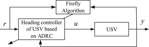
Table 1. USV parameters.
Figure 6. The curve of changing course under FA-ADRC and ADRC.
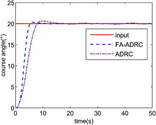
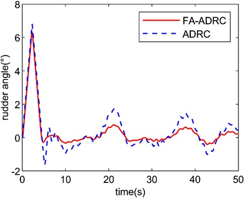
Figure 7. The curve of changing rudder under FA-ADRC and ADRC.
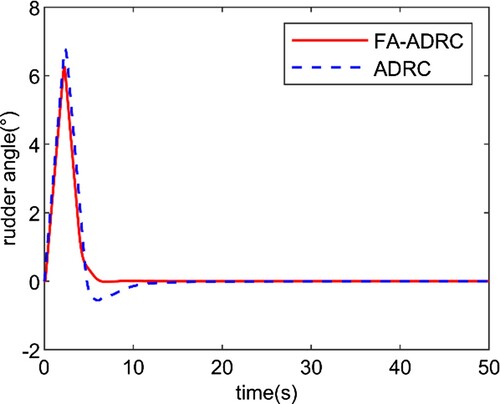
Table 2. Dynamic performance.
Figure 8. The curve of changing course under FA-ADRC and ADRC.
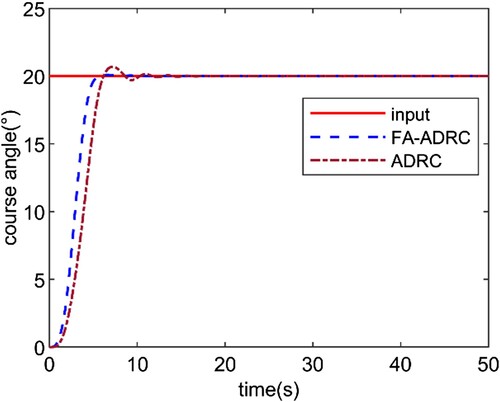
Figure 9. The curve of changing course under FA-ADRC and ADRC.
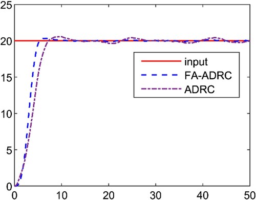
Figure 10. The curve of changing rudder under FA-ADRC and ADRC.