Figures & data
Figure 1. System general diagram.
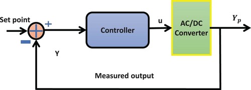
Figure 2. Three-level AC/DC converter.
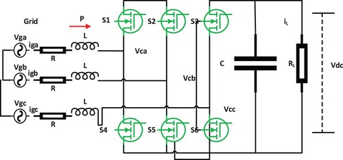
Figure 3. Voltage vectors representation using the Clarke transformation (αβ coordinate system).
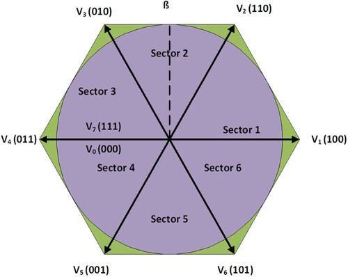
Figure 4. The system Block diagram of EMPSMC scheme.
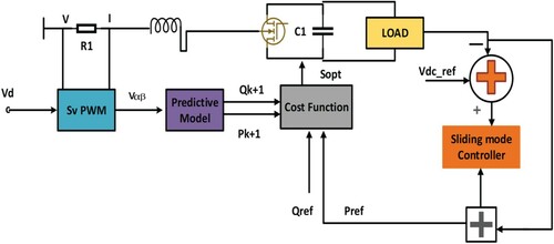
Figure 5. The system Algorithm of EMPSMC Scheme.
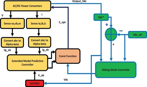
Figure 6. Trajectory Plot like any sliding action into SMC.
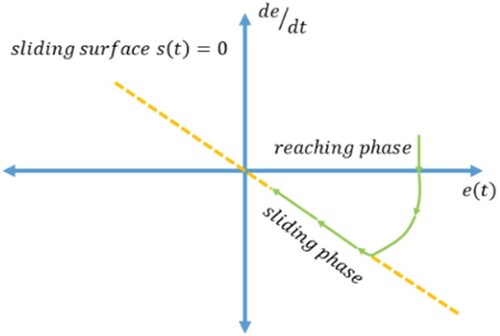
Table 1. Parameter of converter.
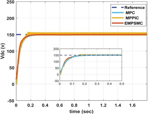
Figure 7. The output response of Step Response of EMPSMC schemes.
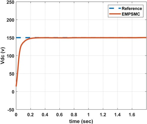
Table 2. Dynamic performance evaluation of EMPSMC and MMPIC
Table 3. System dynamic performance evaluation.
Figure 8. The Output response of the system with EMPSMC plus interference (Disturbance).
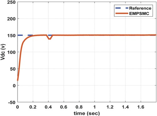
Figure 9. Output reaction to an unpredicted of dc voltage load demand increase (a) demand load increase (b) demand load decrease.
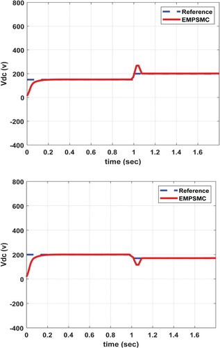
Figure 10. Output reaction to an unpredicted of dc voltage load demand increase (a) Active power increase (b) Active power decrease.
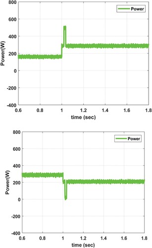
Figure 11. Output reaction to an unpredicted of dc voltage load demand increase (c) Phase A voltage and current increase (d) Phase A voltage and current decreases under EMPSMC.
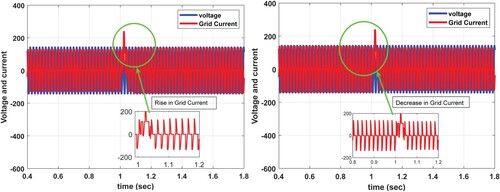
Figure 12. The output response of Step Response of MPPIC schemes.
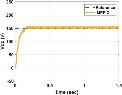
Figure 13. The Output response of the system with MPPIC plus interference (Disturbance).
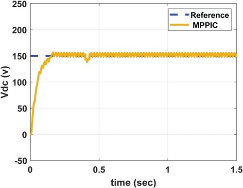
Figure 14. Comparison of EMPC, MPPIC, and MPC.