Figures & data
Figure 1. Topology of the FC-MMC converter.
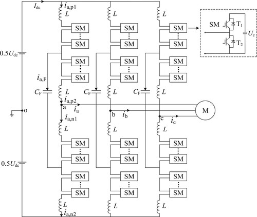
Figure 2. FC-MMC simplified single-phase equivalent circuit diagram.
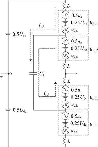
Figure 3. Low-frequency control block diagram of the FC-MMC: (a) Permanent magnet synchronous motor control ; (b) inter-phase capacitive-voltage control; (c) capacitive-voltage control between upper and lower bridge arms; (d) half-bridge arm capacitor voltage control; (e) independent control of the capacitance voltage of the SMs.
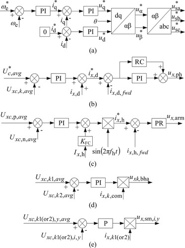
Table 1. Simulation parameters of FC-MMC drive rotary motor.
Figure 4. Simulation results from start-up of the rotary motor to rated speed: (a) turntable motor speed; (b) turntable motor output torque; (c) turntable motor stator current.
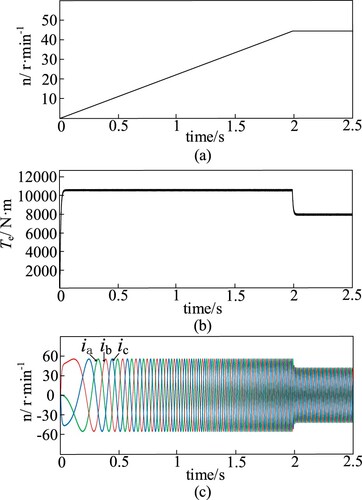
Figure 5. Simulation results of FC-MMC start-up to rated speed: (a) FC-MMC upper and lower half-bridge arm current; (b) FC-MMC upper and lower bridge arm individual SM capacitance voltage; (c) FC-MMC fly span SM capacitor current waveform; (d) FC-MMC fly span SM capacitance voltage waveform.
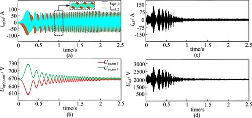
Figure 6. Simulation results of the rotary motor under variable load and stuck drilling conditions: (a) turntable motor speed; (b) turntable motor output torque; (c) turntable motor stator current.
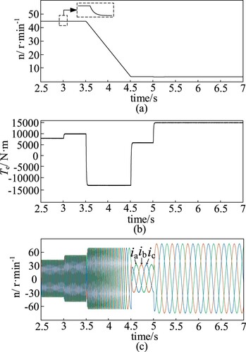
Figure 7. Simulation results of FC-MMC under variable load and stuck drilling conditions: (a) FC-MMC upper and lower half-bridge arm current; (b) FC-MMC upper and lower bridge arm individual SM capacitance voltage; (c) FC-MMC fly span SM capacitor current waveform; (d) FC-MMC fly span SM capacitance voltage waveform.
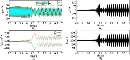
Figure 8. Simulation results of rotary motor inversion condition: (a) turntable motor speed; (b) turntable motor output torque; (c) turntable motor stator current.
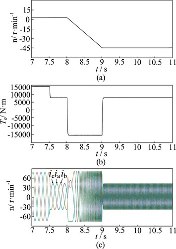
Figure 9. Simulation results of FC-MMC inversion condition: (a) FC-MMC upper and lower half-bridge arm current; (b) FC-MMC upper and lower bridge arm individual SM capacitance voltage; (c) FC-MMC fly span SM capacitor current waveform; (d) FC-MMC fly span SM capacitance voltage waveform.
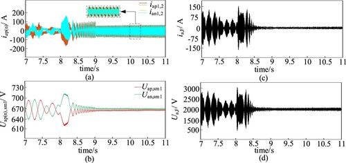
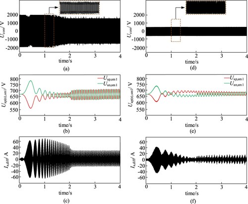
Figure 10. Simulation results comparing MMC with FC-MMC: (a) MMC motor side CMV waveform; (b) MMC upper and lower bridge arm individual SM capacitance voltages; (c) MMC bridge arm circulation; (d) FC-MMC AC side CMV waveform; (e) FC-MMC upper and lower bridge arm individual SM capacitance voltages; (f) FC-MMC bridge arm circulation.