Figures & data
Figure 1. (a) Photograph of a freestanding SWNT buckypaper prepared using the vacuum filtration method. (b) scanning electron microscopy (SEM) image of the buckypaper. (c) Image of SWNT paper strips that are bent around a curved surface. Adapted from Landi et al.Citation25 (d) Cyclic voltammogram of buckypaper measured at 50 mV/s. (e) Galvanostatic charge–discharge curves measured at 5 mA. Adapted from Ci et al.Citation26
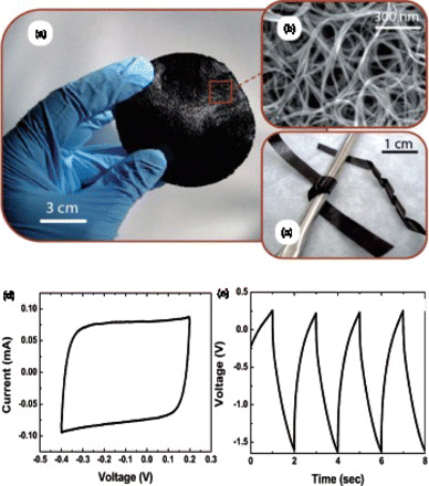
Table 1 Typical results obtained from flexible electrodes assembled using pure carbon nanomaterial for supercapacitors or lithium ion batteries..
Figure 2. Schematic diagram of assembling compact-designed supercapacitor using freestanding flexible SWNT films. Reproduced with permission from Niu et al.Citation33
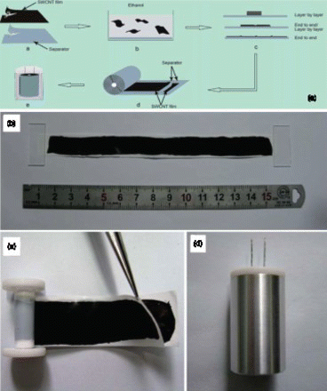
Figure 3. Characterization of self-stacked, solvated graphene (SSG) film. (a,b) photographs of the as-formed flexible SSG film, (c) schematic of the cross-section of the SSG film, (d) CV curves obtained at 10 mV/s and (e) gravimetric capacitances measured at various charge–discharge currents. Reproduced from Yang et al.Citation20
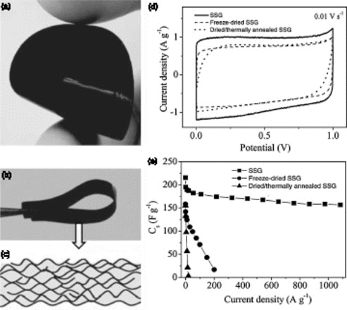
Figure 4. (a) digital and (b) SEM image of CNT and graphene composite electrode (16% CNTs), (c) specific capacitances of nanotube/graphene composites with different nanotube percentages measured within−1.0 to 0 V vs. saturated calomel electrode at 0.1 A/g in 6 M KOH. Adapted from Lu et al.Citation37
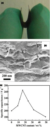
Figure 5. (a) schematic illustration of a paper-based CNTs supercapacitor device, (b) charge–discharge curves in aqueous (lower curve) and nonaqueous (upper curve) electrolytes, (c) CNT weight normalized capacitance as a function of the charge–discharge current, (d) Ragone plot based on active mass, (e) device specific Ragone plot and (f) cycle life of the supercapacitor device. Adapted from Hu and Cui.Citation69
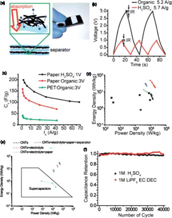
Figure 6. Textile-based electrodes for flexible energy storage: (a) Dipping a piece of textile into aqueous CNT ink. (b) SEM image of CNT-coated textile. (c) SEM image of MnO2–CNT–textile. (d) Specific capacitances at different scan rates for MnO2–CNT–textile electrodes with different areal mass loadings of MnO2. (e) SEM image of graphene-coated textile with uniform MnO2 coating (scale bar 200 μ m). (f) SEM image of a typical microfiber with conformal coating of MnO2 nanostructures (scale bar 5 μ m). Adapted from Yu et al.Citation73
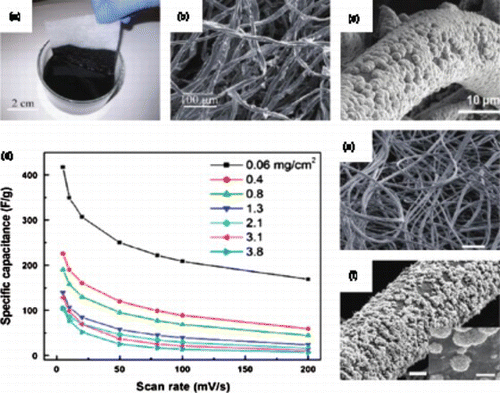
Table 2. Examples of flexible electrodes enabled by carbon nanomaterials for supercapacitors reported in the literature.
Figure 7. (a) Schematic illustration of the structure of the graphene/MnO2/CNT electrode; (b) SEM image and digital image (inserted) of the fabricated flexible electrode; (c) typical stress–strain curve for the flexible electrodes; (d) CV curves for a 30 μ m flexible electrode (2.02 mg/cm2) acquired at different scan rates and (e) comparison of the specific capacitance of the graphene/MnO2/CNTs and the graphene/MnO2 electrodes at different areal densities tested at 50 mV/s. Adapted from Cheng et al.Citation14
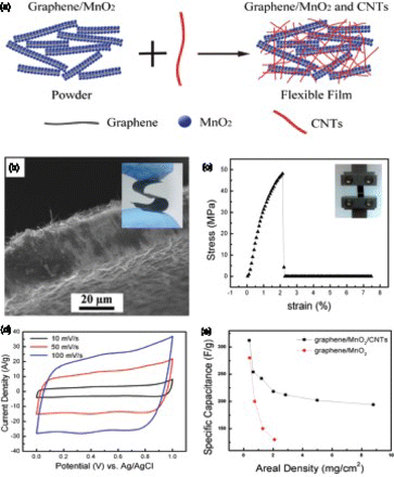
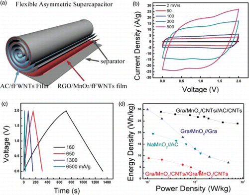
Figure 8. (a) Schematic illustration of the assembly of a flexible asymmetric supercapacitor using the roll-up approach. The positive electrode is a flexible graphene/MnO2/CNTs film and the negative electrode is AC/CNTs flexible film. (b) CV curves of a asymmetric supercapacitor acquired at increasing scan rates from 2 to 500 mV/s in 1 M Na2SO4, (c) galvanostatic charge–discharge curves obtained under different current densities and (d) comparison of the Ragone plots for supercapacitor devices assembled using different materials and/or different electrode structures. Adapted from Cheng et al.Citation15
