
Figures & data
Figure 1. Linear regression fit of steady-state friction coefficients as a function of inverse mean Hertzian contact pressure for as-deposited and annealed ZnO NC-textured nanolaminate. Comparative data are also shown for SC-(0001) and randomly oriented NC ZnO. HRSEM surface images of (b) unworn annealed NC-textured ZnO, and (c) worn nanolaminate with friction coefficient denoted by the filled square symbol at 1.4 GPa−1 in (a). SD is the sliding direction and the rectangle shows location of cross-sectional FIB-cut. (d) Corresponding HRTEM subsurface image acquired along the FIB lift-out in (c) shows a plastically deformed ZnO nanocolumnar grain with intrinsic SFs running parallel to the SD.
Figure 2. (a) Cross-sectional HRTEM image of type-I intrinsic BSF in ZnO, (b) corresponding DFT image, and (c) rigid body displacement with Burgers vector = CB = in (b).
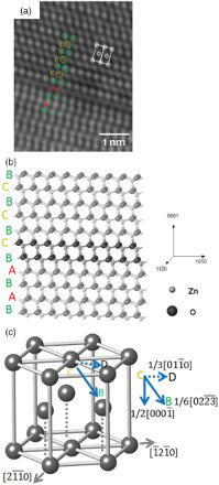
Figure 3. View of {0002} basal planes in a nanocolumnar ZnO grain. (a) Cross-sectional HRTEM image using g=(011¯0) shows subsurface plastic deformation after frictional contact. SD is the sliding direction. (b) Corresponding FFT diffraction pattern shows that the basal planes are observed to be streaked along the [21¯1¯0] beam direction, which is consistent with the presence of stacking faults running normal to the [21¯1¯0] direction. (c) The identification of these dislocations is confirmed in the corresponding Fourier-filtered image using the {0002} diffraction spots, which demonstrate that each PD (shown by arrows) corresponds to one additional (0002) plane. The inset image shows a higher magnification view of the PD with the red arrow. The PD density increases with sliding (multiple slip of PDs by dislocation glide). The dashed lines represent the interface between the protective Pt coating and the ALD ZnO nanolaminate.
![Figure 3. View of {0002} basal planes in a nanocolumnar ZnO grain. (a) Cross-sectional HRTEM image using g=(011¯0) shows subsurface plastic deformation after frictional contact. SD is the sliding direction. (b) Corresponding FFT diffraction pattern shows that the basal planes are observed to be streaked along the [21¯1¯0] beam direction, which is consistent with the presence of stacking faults running normal to the [21¯1¯0] direction. (c) The identification of these dislocations is confirmed in the corresponding Fourier-filtered image using the {0002} diffraction spots, which demonstrate that each PD (shown by arrows) corresponds to one additional (0002) plane. The inset image shows a higher magnification view of the PD with the red arrow. The PD density increases with sliding (multiple slip of PDs by dislocation glide). The dashed lines represent the interface between the protective Pt coating and the ALD ZnO nanolaminate.](/cms/asset/ca61ee27-f475-494c-ba39-4eb1e220686d/tmrl_a_935968_f0003_c.jpg)
Figure 4. View of {011¯0} prismatic planes in a nanocolumnar ZnO grain. (a) Cross-sectional HRTEM image using showing no subsurface plastic deformation in a nanocolumnar grain after frictional contact. SD is the sliding direction. (b) Corresponding FFT diffraction pattern shows that the prismatic planes are not streaked along the [21¯1¯0] beam direction, which is consistent with no stacking faults running normal to the [21¯1¯0] direction. (c) The absence of dislocations is confirmed in the corresponding Fourier-filtered image using the {011¯0} diffraction spots, which translates to no prismatic stacking faults in the worn subsurface (due to its high SFE). The dashed lines represent the interface between the protective Pt coating and ALD ZnO nanolaminate.
![Figure 4. View of {011¯0} prismatic planes in a nanocolumnar ZnO grain. (a) Cross-sectional HRTEM image using showing no subsurface plastic deformation in a nanocolumnar grain after frictional contact. SD is the sliding direction. (b) Corresponding FFT diffraction pattern shows that the prismatic planes are not streaked along the [21¯1¯0] beam direction, which is consistent with no stacking faults running normal to the [21¯1¯0] direction. (c) The absence of dislocations is confirmed in the corresponding Fourier-filtered image using the {011¯0} diffraction spots, which translates to no prismatic stacking faults in the worn subsurface (due to its high SFE). The dashed lines represent the interface between the protective Pt coating and ALD ZnO nanolaminate.](/cms/asset/13a92997-ac10-4984-af41-b50a1e447958/tmrl_a_935968_f0004_c.jpg)