Figures & data
Figure 1. Static Kitagawa–Takahashi plots demonstrating the importance of defect-sensitive design. (a) Comparison between a low- and high-strength material in a stress-based plot. (b) Adapted Kitagawa–Takahashi diagram depicting the influence of fracture toughness and crack length on the fracture strain in a comparison between a low- and high-strength material.
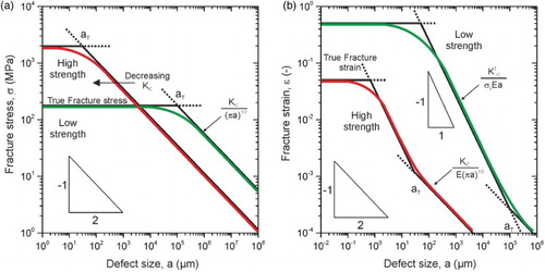
Figure 2. Overview describing the fracture behavior of UFG-iron and nickel. (a) Principal crack planes and crack growth directions investigated for both materials. For simplicity, the crack plane and crack propagation direction of a specimen orientation are abbreviated as A, B or C. Fractographs for crack growth along the elongated microstructure in iron with intergranular fracture (b) and nickel exhibiting transgranular micro-ductile fracture (c). (d) Iron fracture sample with crack-arrestor orientation. (e) Micro-ductile fracture surface found in Ni for the third testing direction. (f) Fracture surface exhibiting various delaminations (some of them are indicated with arrows) typical for iron for the third orientation (crack-divider orientation).
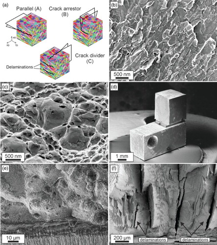
Table 1. Comparison of fracture toughness in UFG-iron and UFG-nickel. The results of Ni were re-calculated into equivalent critical stress intensities derived from crack tip opening displacement measurements [Citation17].
Figure 3. Principal failure types in coarse-grained metals. (a) Micro-ductile fracture through the coalescence of individual voids. (b) De-cohesion process leading to inter- or transgranular fracture. In both cases plasticity, illustrated by the dislocation bundles, is involved.
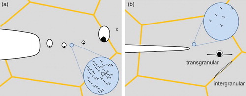
Figure 4. Ductile failure type in NC and UFG metals. (a) Micro-ductile fracture through the coalescence of individual voids. (b) Crack branching into the direction of grain alignment with higher fracture toughness and micro-ductile fracture.
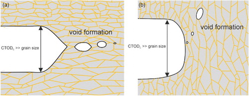
Figure 5. Brittle failure type in NC and UFG metals. (a) Intergranular fracture along the elongated grains. (b) Crack branching into the direction of grain alignment with higher fracture toughness and intergranular fracture. (c) Crack-divider orientation with local crack branching and delamination formation causing a decrease of the through-thickness stress component.
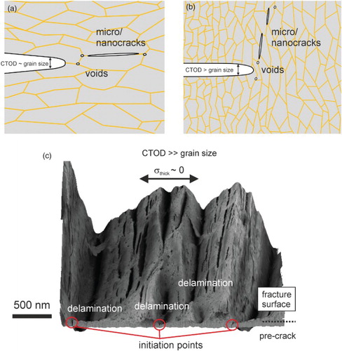
Figure 6. Brittle to ductile transition in SPD-processed iron. (a) Intercrystalline fracture at −196°C. (b) Pure dimple fracture at 200°C. (c) Increase of fracture toughness with increasing temperature with gradual change from grain boundary to dimple fracture.
Figure 7. Changes in fracture toughness in a pearlitic steel due to SPD. In the shear orientation (black dots) fracture toughness progressively decreases with increasing alignment of the lamellar structure due to SPD. In the crack-divider orientation with local crack branching and delamination (open triangles) the fracture toughness remains high.