Figures & data
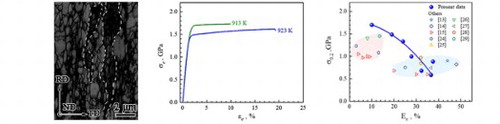
Figure 1. Heterogeneous structure (HS). All for HS after annealing at 923 K except for (c) at 913 K. (a) EBSD quality image. A few areas encircled by dotted line are fiber-like deformed structure. (b), (c), and (d) TEM images showing elongated lamellae and recrystallized grains. Insets in (b) and (c) are SAED pattern. (e) Statistic grain size distribution and aspect ratio (inset) for recrystallized grains. (f) XRD spectrum before and after tensile testing.
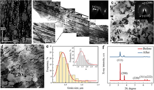
Figure 2. Tensile property. (a) curves after annealing at 913 and 923 K. (b)
curves. (c)
-
curves. (d) (
,
) synergy.
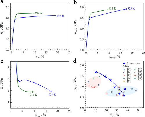
Figure 3. HDI stress. (a) Tensile curve. (b) Hysteresis loop at unload strain of 13%. (c)
versus
curve. (d)
and
versus
curve.
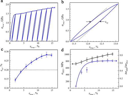
Figure 4. Synchrotron-based in situ XRD tensile loading. (a) XRD spectrum in varying crystal planes. (b) Applied stress vs lattice strain curves. Arrow indicates the onset of micro-yield in (111) grain family. (c) vs
curve.
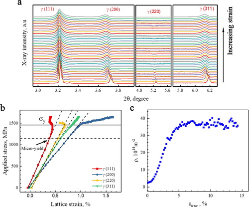
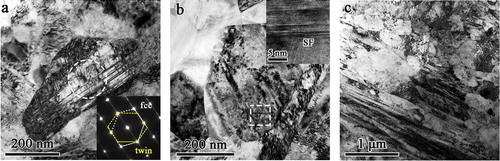
Figure 5. TEM observations of microstructural evolution. (a) Deformation twins. Inset: SAED pattern showing twin relationship. (b) Stacking faults (SFs). Inset: high-resolution TEM image showing lattice image of SF. (c) Tangled dislocations of high density.