Figures & data
Figure 1. Comparisons of the machine configuration, the form of feed material, and the final grain structure among different additive manufacturing processes: (a) additive friction stir deposition, (b) ultrasonic additive manufacturing, (c) cold spray additive manufacturing, and (d) selective laser melting.
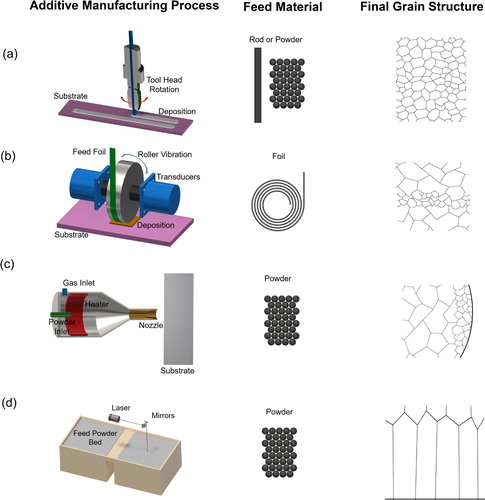
Figure 2. Characteristic microstructures by fusion-based additive manufacturing and AFSD. (a) The microstructure resulting from selective laser melting of AA7075 (left) without and (right) with the addition of Zr nanoparticles. Images reproduced with permission from reference [Citation22]. (b) The microstructure of (top) AA2024 feed-rod by drawing and (bottom) printed AA2024 by AFSD. Images reproduced with permission from reference [Citation36].
![Figure 2. Characteristic microstructures by fusion-based additive manufacturing and AFSD. (a) The microstructure resulting from selective laser melting of AA7075 (left) without and (right) with the addition of Zr nanoparticles. Images reproduced with permission from reference [Citation22]. (b) The microstructure of (top) AA2024 feed-rod by drawing and (bottom) printed AA2024 by AFSD. Images reproduced with permission from reference [Citation36].](/cms/asset/45dcb6cf-6806-4d2b-91e3-fd55303dec59/tmrl_a_1847211_f0002_oc.jpg)
Figure 3. Niche engineering applications for AFSD: (a)–(c) repair and (d)–(e) recycling. (a) A sketch and (b) snapshots of the hole filling process for an AA7075 plate using AFSD. (c) A micrograph of the repair region showing a curved interface between a fine, equiaxed microstructure (filled material) and a rolling microstructure (side wall). Images reproduced with permission from reference [Citation56]. (d) Illustration of the recycling process using AFSD. (e) Tensile properties of the printed AA5083 versus the wrought AA5083. Images reproduced with permission from reference [Citation37].
![Figure 3. Niche engineering applications for AFSD: (a)–(c) repair and (d)–(e) recycling. (a) A sketch and (b) snapshots of the hole filling process for an AA7075 plate using AFSD. (c) A micrograph of the repair region showing a curved interface between a fine, equiaxed microstructure (filled material) and a rolling microstructure (side wall). Images reproduced with permission from reference [Citation56]. (d) Illustration of the recycling process using AFSD. (e) Tensile properties of the printed AA5083 versus the wrought AA5083. Images reproduced with permission from reference [Citation37].](/cms/asset/03ed33ab-ed8b-4b04-9ea4-519f6d1f4afe/tmrl_a_1847211_f0003_oc.jpg)
Figure 4. Thermal and material flow features of AFSD of Al-Mg-Si and Cu. (a) Illustration of the in situ monitoring system for AFSD. The correlation of peak temperature and processing parameters is found to be governed by the material flow behavior. A comparison is drawn between (b) Al-Mg-Si and (c) Cu. Images reproduced with permission from reference [Citation50].
![Figure 4. Thermal and material flow features of AFSD of Al-Mg-Si and Cu. (a) Illustration of the in situ monitoring system for AFSD. The correlation of peak temperature and processing parameters is found to be governed by the material flow behavior. A comparison is drawn between (b) Al-Mg-Si and (c) Cu. Images reproduced with permission from reference [Citation50].](/cms/asset/906700c4-d6f2-48ba-bbb9-69368f2fc7c4/tmrl_a_1847211_f0004_oc.jpg)
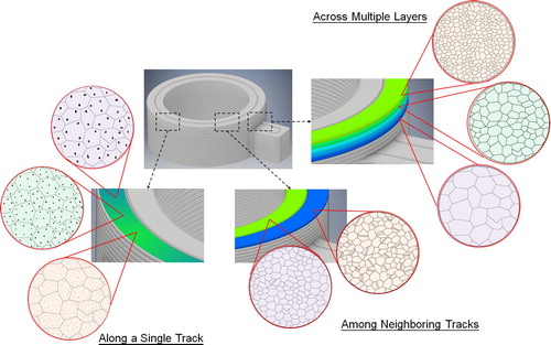
Figure 5. Opportunities of microstructure and mesostructure control unlocked by AFSD. On the microscopic level, examples are given for control of grain size, fraction of special grain boundaries, and precipitate attributes. On the mesoscopic level, examples are given for control along a single deposition track, among neighboring deposition tracks, and across multiple layers.