
Figures & data
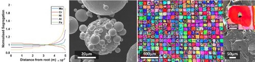
Figure 1. (a) SEM image of FeCrAl powder; (b) powder size distribution measured through SEM imaging; (c) effect of energy density on relative density during deposition; (d) XRD patterns of powder, as-print, and wrought samples.
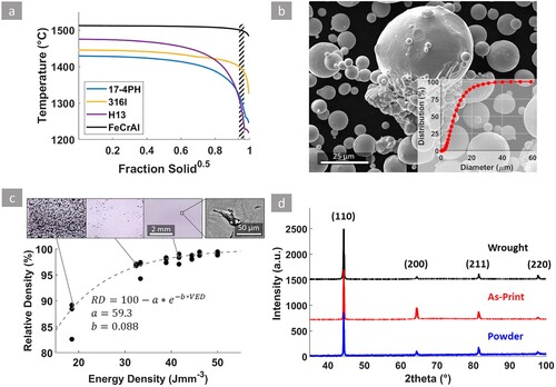
Figure 2. EBSD scan of the as-print specimen parallel (a) and perpendicular (b) to the build direction. Pole figure of EBSD in (a) from grains with (c1) aspect ratio <4, (c2) >4 and (c3) from the combined orientation data of (a) and (b).
Note: Note the legend for the (a) and (b) showing the build direction and scanning directions. (a) and (b) are coloured with inverse pole figure along the build direction and the same scale shown at the bottom left of (a).
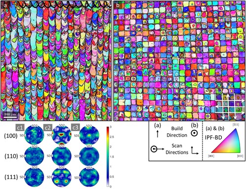
Figure 3. SEM image of (a) five final layers of as-print sample (b) cross-section perpendicular to the build direction; (c), (d) bright-field TEM images of as-print sample; (e) solid-state crack with an EBSD of the region; (f) STEM-EDS line scan across the grain boundary.
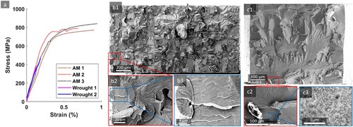
Figure 4. Stress-strain behaviour of FeCrAl alloy in as-print (AM) and Wrought conditions (a) with respective fractographic investigations of sample AM1 and Wrought 1 (b), (c).
Supplemental Material
Download MS Word (6.6 MB)Data availability statement
The raw/processed data required to reproduce these findings is available from the corresponding author upon a reasonable request.