
Figures & data

Table 1. Structural features of the hydrogel materials.
Figure 1. (a) Design principles of the functional hydrogel electrolytes. (b) Schematic structure of the super tough Al3+-alginate/PAAm hydrogel. (c) Mechanical characterisations of the super tough hydrogel. Reproduced with permission from reference [Citation24]. (d) Fabrication and molecular structure of the glycerol–water hydrogel. (e) Anti-freezing performance of the glycerol–water hydrogel. Reproduced with permission from reference [Citation27]. (f) Mechanism of bonding dissimilar polymer networks by using silane coupling agents. (g) Deep-frying hydrogels with/without elastomer coating in mineral oil at 120°C. Reproduced with permission from reference [Citation56]. (h) Working mechanism of the thermoresponsive hydrogel electrolyte via sol–gel transition. (i) Photographs of the reversible sol–gel transition of the thermoresponsive hydrogel electrolyte during heating and cooling cycles. Reproduced with permission from reference [Citation57]. (j) Schematic structure and demonstration of the self-healing PAA-based hydrogel. (k) Self-healing mechanism of the PAA-based hydrogel electrolyte and its ionic conductivity after multiple cutting/healing cycles. Reproduced with permission from reference [Citation64].
![Figure 1. (a) Design principles of the functional hydrogel electrolytes. (b) Schematic structure of the super tough Al3+-alginate/PAAm hydrogel. (c) Mechanical characterisations of the super tough hydrogel. Reproduced with permission from reference [Citation24]. (d) Fabrication and molecular structure of the glycerol–water hydrogel. (e) Anti-freezing performance of the glycerol–water hydrogel. Reproduced with permission from reference [Citation27]. (f) Mechanism of bonding dissimilar polymer networks by using silane coupling agents. (g) Deep-frying hydrogels with/without elastomer coating in mineral oil at 120°C. Reproduced with permission from reference [Citation56]. (h) Working mechanism of the thermoresponsive hydrogel electrolyte via sol–gel transition. (i) Photographs of the reversible sol–gel transition of the thermoresponsive hydrogel electrolyte during heating and cooling cycles. Reproduced with permission from reference [Citation57]. (j) Schematic structure and demonstration of the self-healing PAA-based hydrogel. (k) Self-healing mechanism of the PAA-based hydrogel electrolyte and its ionic conductivity after multiple cutting/healing cycles. Reproduced with permission from reference [Citation64].](/cms/asset/d89311d5-ece9-4b7b-8112-852fc5de1c59/tmrl_a_2059412_f0001_oc.jpg)
Figure 2. Schematics of working principle and basic structure of (a) alkaline Zn-based batteries and (b) rechargeable aqueous Zn-based batteries.
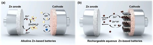
Figure 3. (a) Schematic illustration of the configuration of flexible Zn–MnO2@PEDOT battery. Digital photographs of three flexible Zn–MnO2@PEDOT batteries connected in series powering (b) a neon sign with 45 LEDs and (c) a watch with LED lights. Reproduced with permission from reference [Citation79]. (d) Schematic illustration of the structure of the extremely safe and wearable solid-state ZIB. (e) Cutting test of the flexible solid-state ZIB. (f) Demonstrations of the wearable applications of flexible solid-state ZIBs. Reproduced with permission from reference [Citation81].
![Figure 3. (a) Schematic illustration of the configuration of flexible Zn–MnO2@PEDOT battery. Digital photographs of three flexible Zn–MnO2@PEDOT batteries connected in series powering (b) a neon sign with 45 LEDs and (c) a watch with LED lights. Reproduced with permission from reference [Citation79]. (d) Schematic illustration of the structure of the extremely safe and wearable solid-state ZIB. (e) Cutting test of the flexible solid-state ZIB. (f) Demonstrations of the wearable applications of flexible solid-state ZIBs. Reproduced with permission from reference [Citation81].](/cms/asset/f17c43e8-ac4b-4a81-a760-f05759d130ca/tmrl_a_2059412_f0003_oc.jpg)
Figure 4. (a) Fabrication process of the yarn-shaped Zn–MnO2 battery. (b) Synthesis and molecular structure of the crosslinked PAM-based electrolyte. (c) Photographs of eight yarn-shaped Zn–MnO2 batteries connected in series to power various electroluminescent panels and a long LED belt. Reproduced with permission from reference [Citation46]. (d) Schematic structure of the weavable yarn-shaped NiCo/Zn battery. (e) Demonstration of the industrial weavability and knittability of the textile batteries. (f) Wearable demonstrations of the textile batteries being woven into a wrist band. Reproduced with permission from reference [Citation84]. (g) Schematics of the structure and fabrication of the fibre-shaped Ag–Zn battery with PVA electrolyte. Adapted from Arias et al. [Citation85]. (h) Schematics of the fabrication of the fiber-shaped Zn–air battery with NiCo2O4@N-OCNT-based air electrode and a gel electrolyte. Reproduced with permission from reference [Citation86].
![Figure 4. (a) Fabrication process of the yarn-shaped Zn–MnO2 battery. (b) Synthesis and molecular structure of the crosslinked PAM-based electrolyte. (c) Photographs of eight yarn-shaped Zn–MnO2 batteries connected in series to power various electroluminescent panels and a long LED belt. Reproduced with permission from reference [Citation46]. (d) Schematic structure of the weavable yarn-shaped NiCo/Zn battery. (e) Demonstration of the industrial weavability and knittability of the textile batteries. (f) Wearable demonstrations of the textile batteries being woven into a wrist band. Reproduced with permission from reference [Citation84]. (g) Schematics of the structure and fabrication of the fibre-shaped Ag–Zn battery with PVA electrolyte. Adapted from Arias et al. [Citation85]. (h) Schematics of the fabrication of the fiber-shaped Zn–air battery with NiCo2O4@N-OCNT-based air electrode and a gel electrolyte. Reproduced with permission from reference [Citation86].](/cms/asset/1e530ce4-e81c-4396-bc0d-f62b4c035593/tmrl_a_2059412_f0004_oc.jpg)
Figure 5. (a) Schematic diagrams of the structural evolution of PAM-alginate-based super tough hydrogel electrolyte. (b) Energy dissipation mechanism of the super tough hydrogel electrolyte. Reproduced with permission from reference [Citation88]. (c) The performance of super tough Zn–MnO2 battery tested under foot treading or even under car run-over. (d) Synthesis of the super stretchy PANa hydrogel electrolyte. (e) Schematics of the assembly of the intrinsically super stretchy NiCo/Zn battery. (f) Capacity enhancement ratio of the intrinsically super stretchy battery from 0% to 400% strain. Reproduced with permission from reference [Citation49].
![Figure 5. (a) Schematic diagrams of the structural evolution of PAM-alginate-based super tough hydrogel electrolyte. (b) Energy dissipation mechanism of the super tough hydrogel electrolyte. Reproduced with permission from reference [Citation88]. (c) The performance of super tough Zn–MnO2 battery tested under foot treading or even under car run-over. (d) Synthesis of the super stretchy PANa hydrogel electrolyte. (e) Schematics of the assembly of the intrinsically super stretchy NiCo/Zn battery. (f) Capacity enhancement ratio of the intrinsically super stretchy battery from 0% to 400% strain. Reproduced with permission from reference [Citation49].](/cms/asset/274403be-7009-4c1e-a1df-8f5ac3fac5a0/tmrl_a_2059412_f0005_oc.jpg)
Figure 6. (a) The molecular structure and stretchability properties of the highly concentrated PANa hydrogel electrolyte. Reproduced with permission from reference [Citation20]. (b) Photographs of PAM hydrogels containing various zinc salts at room temperature and −20°C. (c) Photographs of PAM hydrogels with different geometries in different states. Reproduced with permission from reference [Citation91]. (d) Schematics of the synthesis process and multicomplexation of the 3D network structure of PVA-B-G hydrogel. Reproduced with permission from reference [Citation92]. (e) Molecular models of various hydrogels and the simulate interactions between different terminal groups in polymer chains and water molecules. (f) Photographs of the flexible ZAB working at −20°C under various deformation states. Reproduced with permission from reference [Citation90]. (g) Schematics of the strong hydrogen bonds among EG-waPUA, PAM and water molecules in the AF-gel. (h) Freeze-resistant performance of the AF-battery working at subzero temperatures. Reproduced with permission from reference [Citation93]. (i) Synthesis of the anti-freezing CT3G30 hydrogel electrolyte. (j) Photographs of CT3G30 with different geometries in different states. Reproduced with permission from reference [Citation94].
![Figure 6. (a) The molecular structure and stretchability properties of the highly concentrated PANa hydrogel electrolyte. Reproduced with permission from reference [Citation20]. (b) Photographs of PAM hydrogels containing various zinc salts at room temperature and −20°C. (c) Photographs of PAM hydrogels with different geometries in different states. Reproduced with permission from reference [Citation91]. (d) Schematics of the synthesis process and multicomplexation of the 3D network structure of PVA-B-G hydrogel. Reproduced with permission from reference [Citation92]. (e) Molecular models of various hydrogels and the simulate interactions between different terminal groups in polymer chains and water molecules. (f) Photographs of the flexible ZAB working at −20°C under various deformation states. Reproduced with permission from reference [Citation90]. (g) Schematics of the strong hydrogen bonds among EG-waPUA, PAM and water molecules in the AF-gel. (h) Freeze-resistant performance of the AF-battery working at subzero temperatures. Reproduced with permission from reference [Citation93]. (i) Synthesis of the anti-freezing CT3G30 hydrogel electrolyte. (j) Photographs of CT3G30 with different geometries in different states. Reproduced with permission from reference [Citation94].](/cms/asset/c04d0946-6202-4464-98f3-84fed972096e/tmrl_a_2059412_f0006_oc.jpg)
Figure 7. (a) Schematic illustration of the glycerol-based PAM/PAA hydrogel with abundant hydrogen bonding interactions within the polymer chains. (b) Adhesion of the glycerol-based PAM/PAA hydrogel after baking at 70°C for 12 h. (c) A photograph of the battery continuously powering a LED light at 70°C. Reproduced with permission from reference [Citation21]. (d) Synthesis route of the PANa hydrogel electrolyte. (e) Comparison of the real-time water retention of various hydrogels. (f) Long-term cycling performances of the Zn//NiCo battery equipped with the PANa hydrogel electrolyte. Reproduced with permission from reference [Citation23]. (g) Schematic synthesis of porous PVA-based nanocomposite GPE and assembly of the flexible ZAB. (h) Water retention of the nanocomposite PVA hydrogel. (i) GCD curves of various GPEs with a duration of 20 min per cycle. Reproduced with permission from reference [Citation32]. (j) Schematic synthesis of the KI–PVAA–GO GPE and configuration of the assembled flexible batteries. Reproduced with permission from reference [Citation31]. (k) Schematic illustration of the fabrication strategy of the environmental adaptive battery. Reproduced with permission from reference [Citation97].
![Figure 7. (a) Schematic illustration of the glycerol-based PAM/PAA hydrogel with abundant hydrogen bonding interactions within the polymer chains. (b) Adhesion of the glycerol-based PAM/PAA hydrogel after baking at 70°C for 12 h. (c) A photograph of the battery continuously powering a LED light at 70°C. Reproduced with permission from reference [Citation21]. (d) Synthesis route of the PANa hydrogel electrolyte. (e) Comparison of the real-time water retention of various hydrogels. (f) Long-term cycling performances of the Zn//NiCo battery equipped with the PANa hydrogel electrolyte. Reproduced with permission from reference [Citation23]. (g) Schematic synthesis of porous PVA-based nanocomposite GPE and assembly of the flexible ZAB. (h) Water retention of the nanocomposite PVA hydrogel. (i) GCD curves of various GPEs with a duration of 20 min per cycle. Reproduced with permission from reference [Citation32]. (j) Schematic synthesis of the KI–PVAA–GO GPE and configuration of the assembled flexible batteries. Reproduced with permission from reference [Citation31]. (k) Schematic illustration of the fabrication strategy of the environmental adaptive battery. Reproduced with permission from reference [Citation97].](/cms/asset/4d7b6441-91f2-45dc-bc06-d3407b014ae5/tmrl_a_2059412_f0007_oc.jpg)
Figure 8. (a) Cooling recovery function of the thermoresponsive pluronic hydrogel electrolyte. (b) A photograph of the flexible thermo-reversible battery under strong folding. (c) Top-viewed SEM images of the cooling-recovery process of the broken Pluronic-coated electrode area cooling at −5°C. Reproduced with permission from reference [Citation98]. (d) Schematic illustration of the thermoresponsive behaviour of the Zn–MnO2 battery with PNA electrolyte based on sol–gel transition. (e) Thermal self-protection behaviour of the thermoresponsive Zn–MnO2 battery as displayed in charge–discharge cycles at different temperatures. Reproduced with permission from reference [Citation99]. (f) Working mechanism of the thermal self-protective ZIB equipped with hygroscopic hydrogel electrolyte. (g) Demonstration of the reversibility of the thermoresponsive ZIBs. Reproduced with permission from reference [Citation100].
![Figure 8. (a) Cooling recovery function of the thermoresponsive pluronic hydrogel electrolyte. (b) A photograph of the flexible thermo-reversible battery under strong folding. (c) Top-viewed SEM images of the cooling-recovery process of the broken Pluronic-coated electrode area cooling at −5°C. Reproduced with permission from reference [Citation98]. (d) Schematic illustration of the thermoresponsive behaviour of the Zn–MnO2 battery with PNA electrolyte based on sol–gel transition. (e) Thermal self-protection behaviour of the thermoresponsive Zn–MnO2 battery as displayed in charge–discharge cycles at different temperatures. Reproduced with permission from reference [Citation99]. (f) Working mechanism of the thermal self-protective ZIB equipped with hygroscopic hydrogel electrolyte. (g) Demonstration of the reversibility of the thermoresponsive ZIBs. Reproduced with permission from reference [Citation100].](/cms/asset/634878e2-9ae2-4611-ae8d-baf37b6bd090/tmrl_a_2059412_f0008_oc.jpg)
Figure 9. (a) Schematic self-healing mechanism of the Zn(CF3SO3)2/PVA hydrogel electrolyte. (b) Schematic structure of the self-healing ZIBs. Reproduced with permission from reference [Citation44]. (c) Schematic illustration of the synthesis process of the self-healing PANa-Fe3+ hydrogel electrolyte. (d) Fabrication of the intrinsically self-healable NiCo/Zn battery with PANa-Fe3+ hydrogel electrolyte. (e) Self-healing demonstration of the NiCo/Zn battery. Reproduced with permission from reference [Citation19]. (f) Schematic illustration of the self-healing flexible ZIB with PVA–Zn/Mn hydrogel electrolyte. (g) Self-healing demonstration of PVA–Zn/Mn hydrogel electrolyte. (h) Photographs of the self-healing flexible ZIB during four times of cutting and self-healing. Reproduced with permission from reference [Citation101].
![Figure 9. (a) Schematic self-healing mechanism of the Zn(CF3SO3)2/PVA hydrogel electrolyte. (b) Schematic structure of the self-healing ZIBs. Reproduced with permission from reference [Citation44]. (c) Schematic illustration of the synthesis process of the self-healing PANa-Fe3+ hydrogel electrolyte. (d) Fabrication of the intrinsically self-healable NiCo/Zn battery with PANa-Fe3+ hydrogel electrolyte. (e) Self-healing demonstration of the NiCo/Zn battery. Reproduced with permission from reference [Citation19]. (f) Schematic illustration of the self-healing flexible ZIB with PVA–Zn/Mn hydrogel electrolyte. (g) Self-healing demonstration of PVA–Zn/Mn hydrogel electrolyte. (h) Photographs of the self-healing flexible ZIB during four times of cutting and self-healing. Reproduced with permission from reference [Citation101].](/cms/asset/4aa6b725-93b0-430b-94db-3c2f6bb75cc7/tmrl_a_2059412_f0009_oc.jpg)