Figures & data

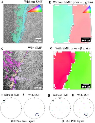
Figure 1. (a) Schematic showing the solidification process of L-DED under a 0.55 T transverse SMF, where (c) the thermoelectric current and thermoelectric magnetic force are illustrated in the solidification front. (b) Distribution of magnetic field intensity. (d) and (g) OM images; (e) and (h) β grains microscopy images; (f) and (i) Histograms of β grain size.
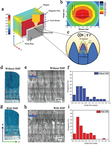
Figure 2. (a) and (b) XRD 001 pole figures (PFs) of the β phase in samples without (a) and with (b) SMF. (c) and (d) XRD 110 PFs of the β phase in samples without (c) and with (d) SMF. (e) and (f) Standard poles of <100> and <110> in 001 PFs (e) and 110 PFs (f). (g) Volume percent of preferred orientations of samples without and with SMF along (001) <100> fiber texture.
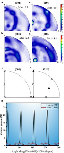
Figure 3. Multi-scale microstructure characterizations of Ti64 sample without (a–d) and with (e–h) SMF: (a, e) SEM-BSE; (b, f) EBSD inverse pole figures (IPFs); (c, g) (0002) α PFs of α phase to corresponding (b) and (f); (d, h) TEM-DF observations.
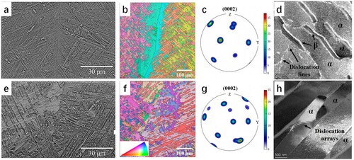
Figure 4. (a) Stress-strain curves of the samples without and with SMF performed on transverse (V*) and longitudinal (H*) directions, respectively. (b) Comparison of UTS vs. εf of Ti64 with related studies [Citation6,Citation9,Citation22–27]. (c, d and g, h) Fracture morphology of samples without and with SMF; (e, f and i, j) TEM-DF observations of the fractured longitudinal samples without (e, f) and with (i, j) SMF, which is located 1 mm below the fracture.
![Figure 4. (a) Stress-strain curves of the samples without and with SMF performed on transverse (V*) and longitudinal (H*) directions, respectively. (b) Comparison of UTS vs. εf of Ti64 with related studies [Citation6,Citation9,Citation22–27]. (c, d and g, h) Fracture morphology of samples without and with SMF; (e, f and i, j) TEM-DF observations of the fractured longitudinal samples without (e, f) and with (i, j) SMF, which is located 1 mm below the fracture.](/cms/asset/b85f408e-9e79-47c3-bd39-5d952d130c0e/tmrl_a_2064195_f0004_oc.jpg)
Table 1. Tensile behavior of L-DED Ti64 without or with SMF.
Table 2. Physical parameters of Ti-6Al-4V.
Figure 5. (a) and (c) EBSD IPFs of GBs α. (b) and (d) Reconstructed EBSD IPFs of β in samples. (e) and (f) 0002 PFs of the GBs α corresponding to (a) and (c). (g) and (h): 110 PFs of the reconstructed β phase corresponding to (b) and (d).