
Figures & data
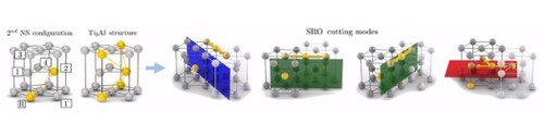
Figure 1. Binding energies of Al pairs in α-Ti as a function of distance between solute atoms (a). Sketch of the hcp lattice indicating the five most strongly interacting NN configurations with the reference solute atom lying at R position (b). Crystal structure of the intermetallic
compound achieved by multiplication of the second and third NN Al pairs (c).
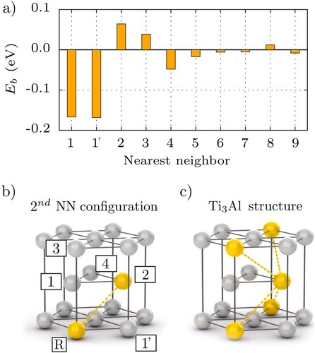
Figure 2. (a) Three geometrically possible prismatic and basal cutting modes of the second NN solute pair in α-Ti. (b) Initial and final
positions of
screw dislocation gliding next to isolated Al atom or cutting the second NN Al pair along prismatic and basal modes I–III.
and
indicate the position (normalized by the lattice parameter a) of solute atoms along dislocation line in the simulation box. Ti atoms belonging to different
are plotted with open or full-colored circles. Solute atoms are denoted by yellow color. The corresponding minimum energy paths of particular prismatic and basal slip modes are given in (c), with the Peierls energy barriers of pure Ti marked by dashed lines.
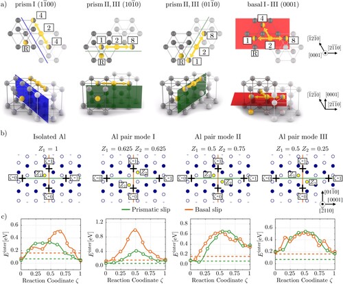
Table 1. Activation energies and its difference
relative to pure Ti for a
screw dislocation gliding in prismatic and basal planes in pure Ti and Ti–Al systems with distinct configurations of solute atoms. Activation energies are given in meV and are calculated for a single dislocation of length (Figure (b)).
Figure 3. Core structure of the screw dislocation gliding on basal plane along isolated Al atom or cutting the second NNN Al pairs with I–III cutting modes. Selected states are the initial, maximum energy and final configuration of each glide mode from Figure . The arrows between atomic columns are proportional to the differential displacement created by the dislocation in the
direction. Displacement smaller than 0.1b is not shown. The contour map shows the dislocation density according to the Nye tensor.
![Figure 3. Core structure of the 〈a〉 screw dislocation gliding on basal plane along isolated Al atom or cutting the second NNN Al pairs with I–III cutting modes. Selected states are the initial, maximum energy and final configuration of each glide mode from Figure 3. The arrows between atomic columns are proportional to the differential displacement created by the dislocation in the [2¯110] direction. Displacement smaller than 0.1b is not shown. The contour map shows the dislocation density according to the Nye tensor.](/cms/asset/0bbf6ff0-15ac-41c5-ac95-c9433d1bcbdf/tmrl_a_2169082_f0003_oc.jpg)
Figure 4. Core structure of the screw dislocation gliding on prismatic plane along isolated Al atom or cutting the second NNN Al pairs with I–III cutting modes. Selected states are the initial, maximum energy and final configuration of each glide mode from Figure . The arrows between two atomic columns are proportional to the differential displacement created by the dislocation in the
direction. Displacement smaller than 0.1b is not shown. The contour map shows the dislocation density according to the Nye tensor.
![Figure 4. Core structure of the 〈a〉 screw dislocation gliding on prismatic plane along isolated Al atom or cutting the second NNN Al pairs with I–III cutting modes. Selected states are the initial, maximum energy and final configuration of each glide mode from Figure 3. The arrows between two atomic columns are proportional to the differential displacement created by the dislocation in the [2¯110] direction. Displacement smaller than 0.1b is not shown. The contour map shows the dislocation density according to the Nye tensor.](/cms/asset/e361e808-82ab-4e7c-8e8c-f3146c92b5f1/tmrl_a_2169082_f0004_oc.jpg)
Data availability
All data needed to evaluate the conclusions in the paper are present in the paper and/or the Supplementary Materials. Any additional details are available from the corresponding author upon reasonable request.