Figures & data
Figure 1. Our binary pattern encoded on a green marker. The pattern is composed of 16 sequences of 8-bit codes, where each bit is represented by an oriented elliptical feature. The elliptical features in our marker, representing 0s and 1s, were designed to be distinctive even under challenging conditions such as when the surgical tool is at steep angles. Each feature is also associated to a unique ID, to store its 3D position (X, Y, Z) which calculated using the radius and the position of the feature in the marker. The 3D positions remained fixed, and are used by a PnP solver to estimate the marker’s pose.
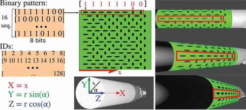
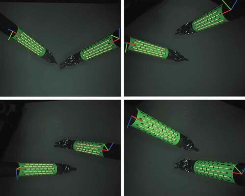
Figure 2. Surgical tool tracking using our enhanced marker.
Figure 3. Ex vivo experiment, where the surgical tool moves over a porcine liver, and illustration of the coordinate frames and their transformations. The coordinates frames represent the Marker (M), the KeyDot (K), and the Laparoscope (L).
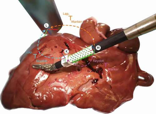
Figure 4. Results on ex vivo experiment, where a surgical tool of the da Vinci® robot goes through a predefined set of illumination conditions and poses. At each pose two images are captured, one for our binary marker, shown on the right column, and one for the state-of-the-art marker (Zhang et al. Citation2017), shown on the left column. The surgical tool are moving over an ex vivo porcine liver.
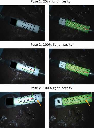
Figure 5. Results on simulation experiment.
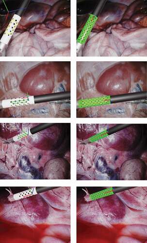
Figure 6. Results on tracking multiple tools.