Figures & data
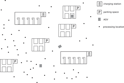
Figure 1. An illustration of a typical two-level model of AGV operations consisting of charging hubs (facilities), parking spaces (substations) and processing locations. The problem of optimal location of these charging hubs and parking spaces translates into a two-level facility location problem.

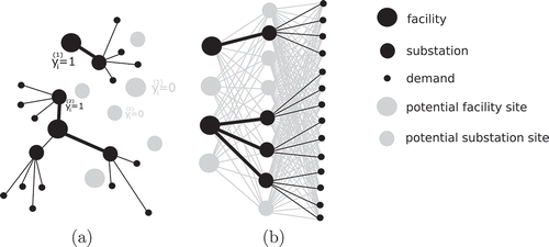
Figure 2. Illustrations of the geometric interpretation (a) and the layered network interpretation (b) of the two-level facility location problems.

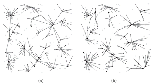
Figure 3. An illustration of the optimal network designs for random geometric networks with 25 facility sites, 50 substation sites and 200 demands. Illustration (a) represents the optimal network design obtained for the first formulation, while illustration (b) depicts the optimal network design for the second formulation.

Table 1. Computational results obtained for Problem 1 and Problem 2 derived from the same geometric network with 25 facility sites, 50 sites and 200 demands.
Table 2. Computational results obtained for Problem 1 and Problem 2 derived from the same uniformly distributed sites with 25 facility sites, 50 substation sites and 200 demands.
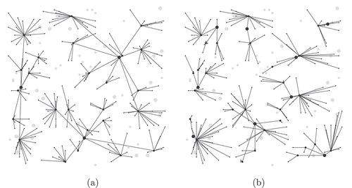
Figure 4. An illustration of the optimal network designs for facilities, substations and demands distributed uniformly on a regular mesh with 25 facility sites, 50 substation sites and 200 demands. Illustration (a) represents the optimal network design obtained for the first formulation, while illustration (b) depicts the optimal network design for the second formulation.

