Figures & data
Table 1. Typical features of modern air brake systems.
Table 2. Methods to solve brake pipe models.

![Figure 3. Brake pipe lumped parameter model [Citation56].](/cms/asset/b5121b49-1d23-4bdc-a386-fea480591e62/tjrt_a_2006808_f0003_b.gif)
![Figure 4. Brake pipe lumped parameter model [Citation84].](/cms/asset/a13291e6-764b-4646-8ca0-67bc045f550e/tjrt_a_2006808_f0004_b.gif)
![Figure 5. Empirical function: (a) pressure drop and vehicle speed to vehicle deceleration [Citation84], and (b) brake cylinder pressure to brake pipe pressure [Citation77].](/cms/asset/7939f330-6e2e-445d-9525-8a92554e0b83/tjrt_a_2006808_f0005_oc.jpg)
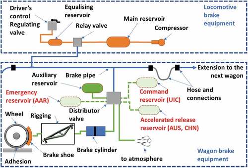
![Figure 6. Interconnection logics of railway brake control valve (revised from [Citation53]).](/cms/asset/9519e9e3-9c13-4f65-8bde-3c73f6c7d47c/tjrt_a_2006808_f0006_oc.jpg)
![Figure 7. Wagon brake system diagram [Citation101], ∅1∼∅17 are various orifices.](/cms/asset/bcd1637e-d1b7-401a-9756-f5ce45712a65/tjrt_a_2006808_f0007_oc.jpg)
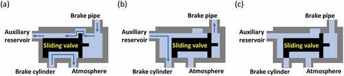
![Figure 8. Stages in empirical models for valve motions [Citation52].](/cms/asset/30c78956-9ae2-4d0e-b345-c3f8be59facb/tjrt_a_2006808_f0008_oc.jpg)
![Figure 10. Orifices: (a)square and sharp edged orifices and (b) orifice flow [Citation48].](/cms/asset/1d423ea8-b6de-4cac-8d42-bc987010a5e2/tjrt_a_2006808_f0010_oc.jpg)
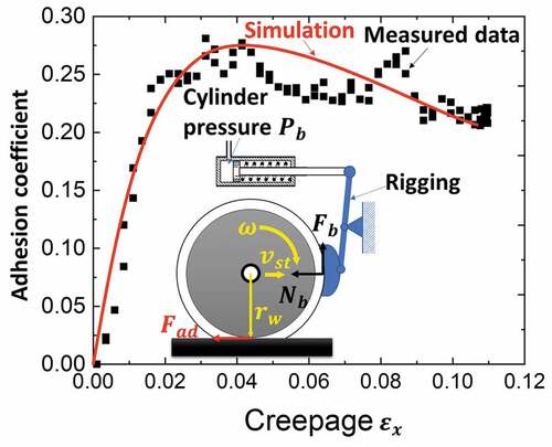
![Figure 12. Brake simulations with wheel-rail adhesion [Citation45].](/cms/asset/0bf3e290-a666-43c8-b5e5-2d3eb0e32264/tjrt_a_2006808_f0012_oc.jpg)