541
Views
1
CrossRef citations to date
0
Altmetric
Research Article

Numerical modelling of pollutant formation in a lifted methane–air vertical diffusion flame

ORCID Icon, , , & | (Reviewing Editor)
Article: 1302543 | Received 07 Dec 2016, Accepted 24 Feb 2017, Published online: 20 Mar 2017

Figures & data

Figure 1. Computational flow domain and boundary conditions.

Note: Dimensions in mm.
Figure 1. Computational flow domain and boundary conditions.

Figure 2. Hex mesh of the flow domain generated using ANSYS ICEM meshing software.

Figure 2. Hex mesh of the flow domain generated using ANSYS ICEM meshing software.

Figure 3. Predictions of (a) axial velocity, (b) radial velocity, (c) velocity at pipe exit and (d) axial temperature, for 50, 100, and 180 K mesh sizes showing meshing independence.
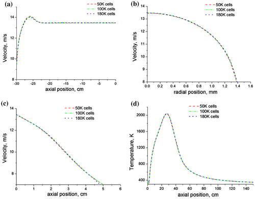
Figure 3. Predictions of (a) axial velocity, (b) radial velocity, (c) velocity at pipe exit and (d) axial temperature, for 50, 100, and 180 K mesh sizes showing meshing independence.

Figure 4. Axial predictions of (a) turbulent kinetic energy, (b) turbulent dissipation rate and (c) turbulent intensity for a methane–air jet diffusion flame at Re = 4,221 using the three turbulence models.
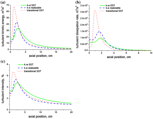
Figure 4. Axial predictions of (a) turbulent kinetic energy, (b) turbulent dissipation rate and (c) turbulent intensity for a methane–air jet diffusion flame at Re = 4,221 using the three turbulence models.

Figure 5. Radial predictions of the mean mixture fraction at (a) x/di = 9, (b) x/di = 60, and (c) x/di = 170 for a methane–air jet diffusion flame at Re = 4,221 using the three turbulence models.
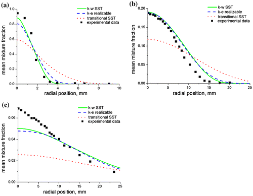
Figure 5. Radial predictions of the mean mixture fraction at (a) x/di = 9, (b) x/di = 60, and (c) x/di = 170 for a methane–air jet diffusion flame at Re = 4,221 using the three turbulence models.
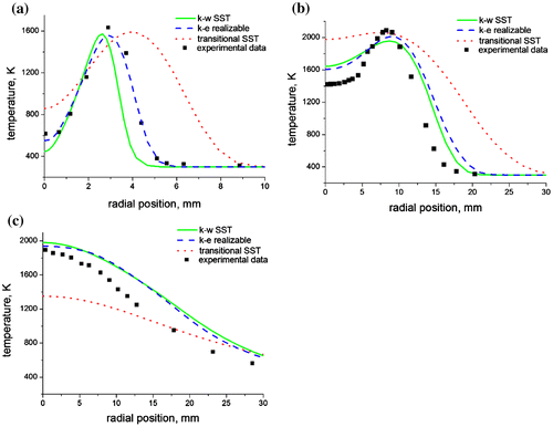
Figure 6. Radial predictions of temperature at (a) x/di = 9, (b) x/di = 60, and (c) x/di = 170 for a methane–air jet diffusion flame at Re = 4,221 using the three turbulence models.
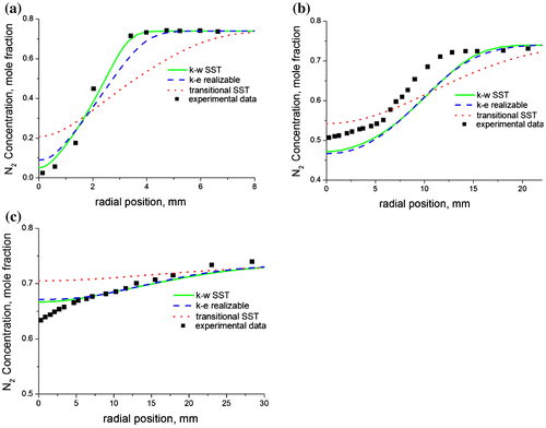
Figure 6. Radial predictions of temperature at (a) x/di = 9, (b) x/di = 60, and (c) x/di = 170 for a methane–air jet diffusion flame at Re = 4,221 using the three turbulence models.
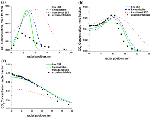
Figure 7. Radial predictions of the nitrogen concentrations at (a) x/di = 9, (b) x/di = 60, and (c) x/di = 170 for a methane–air jet diffusion flame at Re = 4,221 using the three turbulence models.

Figure 7. Radial predictions of the nitrogen concentrations at (a) x/di = 9, (b) x/di = 60, and (c) x/di = 170 for a methane–air jet diffusion flame at Re = 4,221 using the three turbulence models.

Figure 8. Radial predictions of the carbon dioxide concentrations at (a) x/di = 9, (b) x/di = 60, and (c) x/di = 170 for a methane–air jet diffusion flame at Re = 4,221 using the three turbulence models.

Figure 8. Radial predictions of the carbon dioxide concentrations at (a) x/di = 9, (b) x/di = 60, and (c) x/di = 170 for a methane–air jet diffusion flame at Re = 4,221 using the three turbulence models.
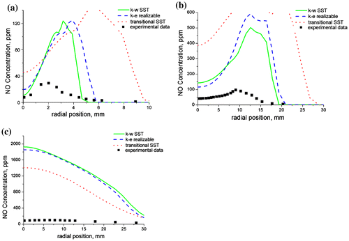
Figure 9. Radial predictions of the nitrogen oxide concentration at (a) x/di = 9, (b) x/di = 60, and (c) x/di = 170 for a methane–air jet diffusion flame at Re = 4,221 using the three turbulence models.
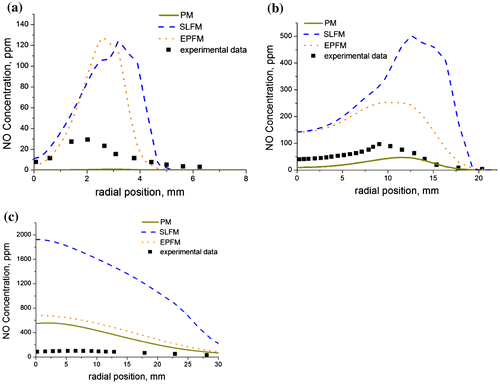
Figure 9. Radial predictions of the nitrogen oxide concentration at (a) x/di = 9, (b) x/di = 60, and (c) x/di = 170 for a methane–air jet diffusion flame at Re = 4,221 using the three turbulence models.

Figure 10. Radial predictions of the nitrogen oxide concentration at (a) x/di = 9, (b) x/di = 60, and (c) x/di = 170 for a methane–air jet diffusion flame at Re = 4,221 using three combustion models.

Figure 10. Radial predictions of the nitrogen oxide concentration at (a) x/di = 9, (b) x/di = 60, and (c) x/di = 170 for a methane–air jet diffusion flame at Re = 4,221 using three combustion models.