554
Views
0
CrossRef citations to date
0
Altmetric
Research Article

Development of static type garbage treatment system

ORCID Icon, , & | (Reviewing Editor)
Article: 1322766 | Received 11 Jan 2017, Accepted 18 Apr 2017, Published online: 31 May 2017

Figures & data

Table 1. Conditions of garbage treatment

Figure 1. Time course of moisture content.

Note: For the captions A to E, refer to Table .
Figure 1. Time course of moisture content.

Figure 2. Time course of decomposition rate of organic matter.
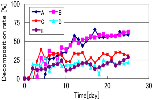
Note: For the captions A to E, refer to Table .
Figure 2. Time course of decomposition rate of organic matter.

Figure 3. Time course of the weight the virtual reactors with various materials for wall.
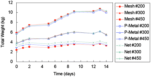
Note: The number in the legend symbol means the depth of the heap (bulking agent/microbial accelerator/garbage) in mm. Legend: “Mesh” is metal mesh, “P-Metal” is punching metal and “Net” is the cleaning net installed at the bottom of each reactor.
Figure 3. Time course of the weight the virtual reactors with various materials for wall.

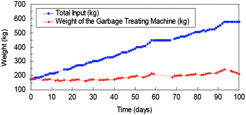
Figure 4. Time course of the garbage treatment experiment with a test model.

Figure 4. Time course of the garbage treatment experiment with a test model.

Figure 5. An example of the time course of garbage decomposition rate and the colony number in the static type treating system.
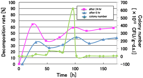
Figure 5. An example of the time course of garbage decomposition rate and the colony number in the static type treating system.
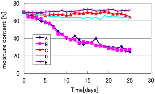
Table 2. The methods of fluorescence observation and their conditions

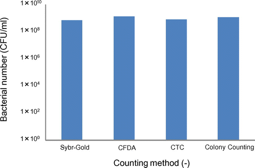
Figure 6. The total number of bacteria in the fining sample (day 13).

Figure 6. The total number of bacteria in the fining sample (day 13).

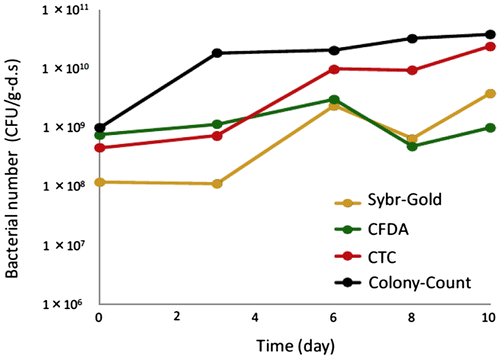
Figure 7. Time course of the total number in the suspension sample.

Figure 7. Time course of the total number in the suspension sample.

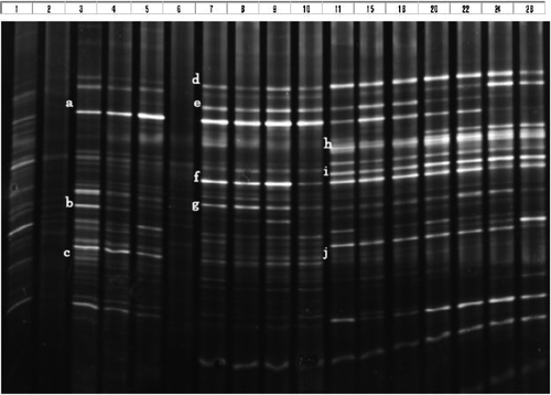
Figure 8. The DGGE analysis on the residue of the static type garbage treating for 28 days.

Figure 8. The DGGE analysis on the residue of the static type garbage treating for 28 days.