4,032
Views
2
CrossRef citations to date
0
Altmetric
Research Article

Assessment of pile response due to deep excavation in close proximity—A case study based on DTL3 Tampines West Station

& | (Reviewing Editor)
Article: 1014247 | Received 02 Sep 2014, Accepted 25 Jan 2015, Published online: 20 Mar 2015

Figures & data

Figure 1. Cracks on external walls and columns of buildings caused by deep excavation.

Figure 1. Cracks on external walls and columns of buildings caused by deep excavation.

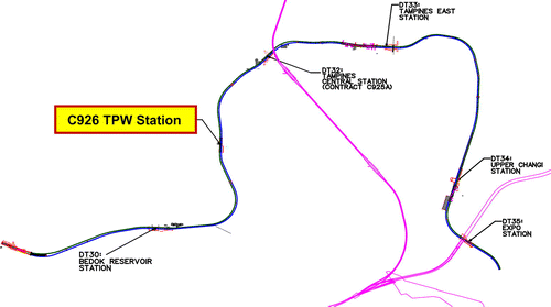
Figure 2. Location map for DTL3 C926 TPW Station.

Figure 2. Location map for DTL3 C926 TPW Station.

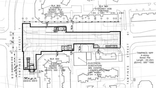
Figure 3. Plan showing proximity of the TPW Station to the HDB Blocks.

Figure 3. Plan showing proximity of the TPW Station to the HDB Blocks.

Table 1. Summary table of soil parameters

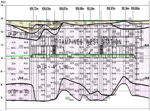
Figure 4. Geological profiles along TPW Station.

Figure 4. Geological profiles along TPW Station.

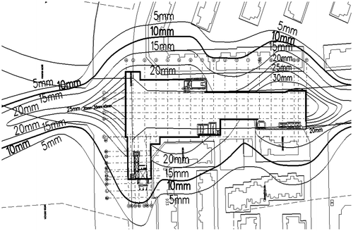
Figure 5. Settlement contour around TPW Station due to deep excavation.

Figure 5. Settlement contour around TPW Station due to deep excavation.

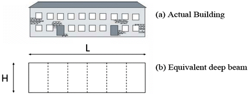
Figure 6. Building idealization for Stage II damage assessment.

Figure 6. Building idealization for Stage II damage assessment.

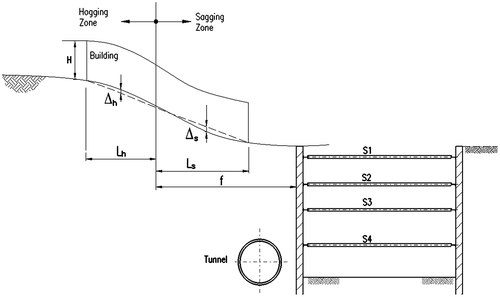
Figure 7. Building deformation—partitioning between sagging and hogging.

Figure 7. Building deformation—partitioning between sagging and hogging.

Table 2. Relationship between category of damage and limiting tensile strain

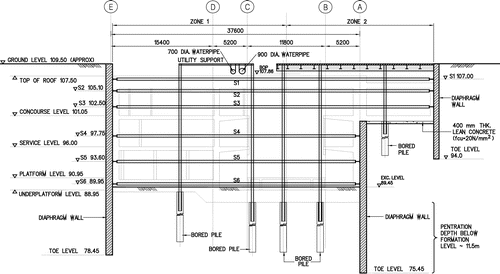
Figure 8. Typical sections of ERSS for TPW station adjacent to the HDB Block 803.

Figure 8. Typical sections of ERSS for TPW station adjacent to the HDB Block 803.

Figure 9. Finite element meshes showing the pile foundation arrangement adjacent to a deep excavation (encircled closest pile considered in this study).
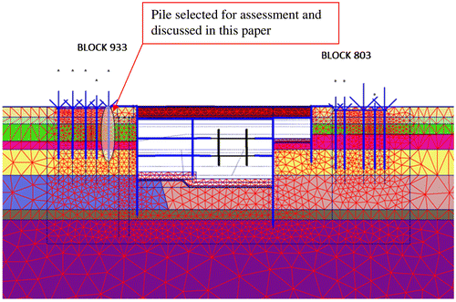
Figure 9. Finite element meshes showing the pile foundation arrangement adjacent to a deep excavation (encircled closest pile considered in this study).

Figure 10. Vertical soil displacements due to the complete cycle of stage excavation and construction of the station structure.
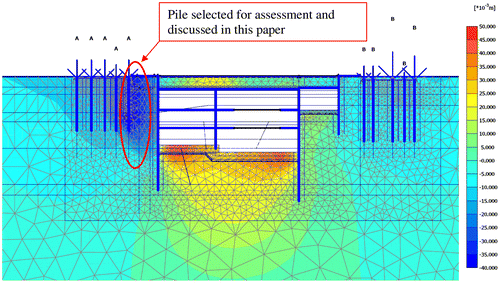
Figure 10. Vertical soil displacements due to the complete cycle of stage excavation and construction of the station structure.
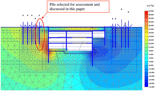
Figure 11. Horizontal soil displacements due to the complete cycle of stage excavation and construction of the station structure.

Figure 11. Horizontal soil displacements due to the complete cycle of stage excavation and construction of the station structure.

Figure 12. Effective normal stress distribution on the pile closest to the excavation before and after excavation.
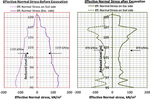
Figure 12. Effective normal stress distribution on the pile closest to the excavation before and after excavation.

Figure 13. Comparison of development of skin friction on the pile closest to the excavation before and after excavation.
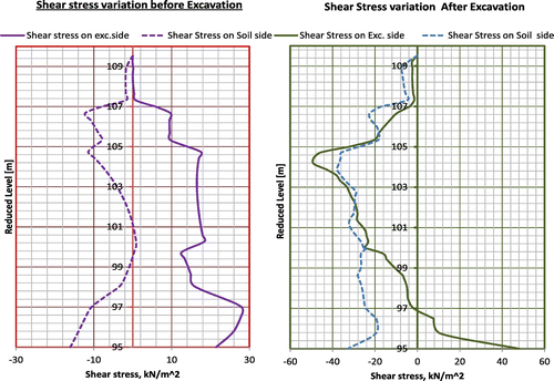
Figure 13. Comparison of development of skin friction on the pile closest to the excavation before and after excavation.

Figure 14. Variation of pile axial force with depth at the pile closest to the retaining wall before and after excavation.
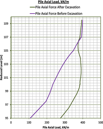
Figure 14. Variation of pile axial force with depth at the pile closest to the retaining wall before and after excavation.
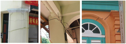
Table 3. Summary table of comparison of pile shaft friction and factor of safety for the cases before and after excavation

Table 4. Summary table of comparison of pile shaft friction and factor of safety for the cases before and after excavation

Table 5. Summary table of impact on the pile foundation on HDB Block 803 and 933