3,752
Views
2
CrossRef citations to date
0
Altmetric
Research Article

Performance evaluation of aeroderivative gas turbine models derived from a high bypass turbofan for industrial power generation

ORCID Icon, & | (Reviewing Editor)
Article: 1301235 | Received 17 Oct 2016, Accepted 27 Feb 2017, Published online: 13 Mar 2017

Figures & data

Table 1. Turbomatch inputs for design point and cruise conditions (Palmer, Citation1999; Roux, Citation2011; Walsh & Fletcher, Citation2004)

Figure 1. Brick code arrangements for the turbofan model.

Figure 1. Brick code arrangements for the turbofan model.

Table 2. Assumed values for the turbofan turbomatch simulation related to GT models (Lefebvre, Citation1998; Nkoi et al., Citation2013a; Palmer, Citation1999; Sethi, Citation2014)

Figure 2. Block diagram of aeroderivative and turbomatch brick arrangement for (a) and (b) Model I—Two-spool with FPT, (c) and (d) Model II—Two-spool with integrated power turbine on LPS, and (e) and (f) Model III—Single spool with FPT.
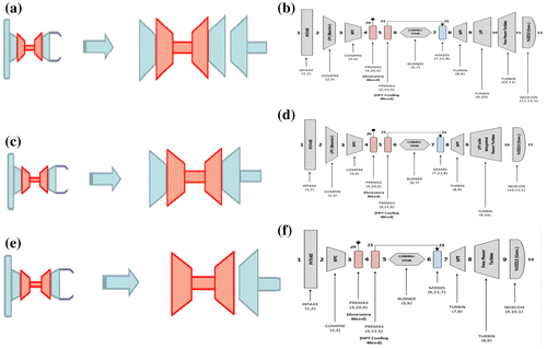
Figure 2. Block diagram of aeroderivative and turbomatch brick arrangement for (a) and (b) Model I—Two-spool with FPT, (c) and (d) Model II—Two-spool with integrated power turbine on LPS, and (e) and (f) Model III—Single spool with FPT.

Table 3. Comparison of simulated results for the HPTE with published data (CFM International, Citation2000; Palmer, Citation1999; Roux, Citation2011; Safran Snecma, Citation2011)

Table 4. Comparison of simulated results at DP for the aeroderivative Models I, II & III

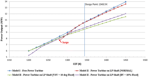
Figure 3. Part-load performance (off design): power output vs. combustion outlet temperature (COT).

Figure 3. Part-load performance (off design): power output vs. combustion outlet temperature (COT).

Figure 4a. Part-load performance (off design): thermal efficiency vs. combustion outlet temperature.
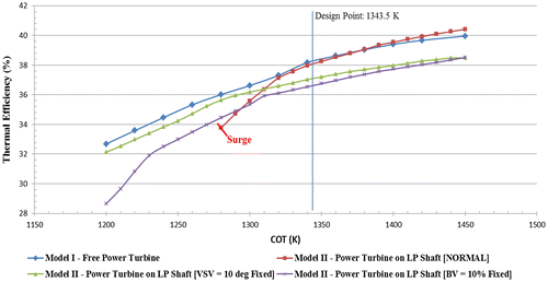
Figure 4a. Part-load performance (off design): thermal efficiency vs. combustion outlet temperature.

Figure 4b. Part-load performance (off design): specific fuel consumption vs. combustion outlet temperature.
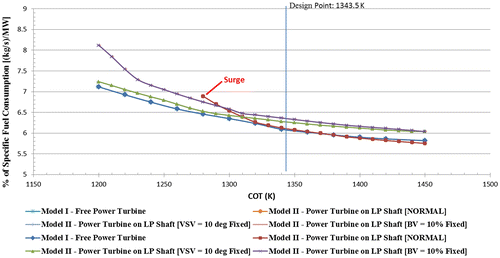
Figure 4b. Part-load performance (off design): specific fuel consumption vs. combustion outlet temperature.
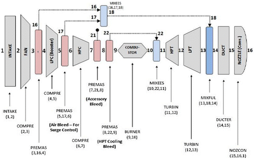
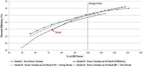
Figure 5. Part-load performance (off design): Thermal efficiency vs. % DP of power.

Figure 5. Part-load performance (off design): Thermal efficiency vs. % DP of power.

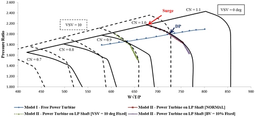
Figure 6. LP map and running lines for Models I and II at pat load performance.

Figure 6. LP map and running lines for Models I and II at pat load performance.

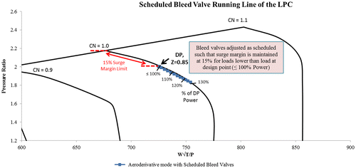
Figure 7. LP compressor map and running line with scheduled bleed valves for Model II.

Figure 7. LP compressor map and running line with scheduled bleed valves for Model II.

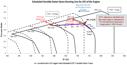
Figure 8. LP Compressor map and running line with scheduled variable stator vanes for Model II.

Figure 8. LP Compressor map and running line with scheduled variable stator vanes for Model II.