1,756
Views
34
CrossRef citations to date
0
Altmetric
Research Article

Comparative performances evaluation of FACTS devices on AGC with diverse sources of energy generation and SMES

& | (Reviewing Editor)
Article: 1318466 | Received 22 Dec 2016, Accepted 07 Apr 2017, Published online: 26 Apr 2017

Figures & data

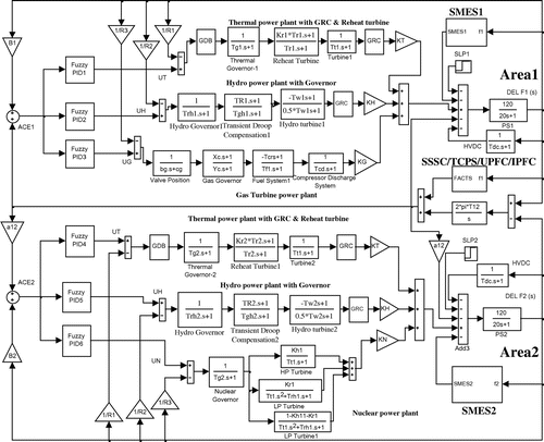
Figure 1. Transfer function model of multi-source multi-area power system.

Figure 1. Transfer function model of multi-source multi-area power system.

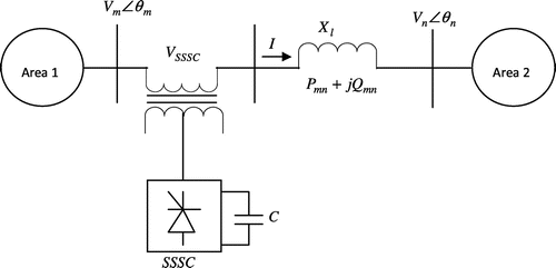
Figure 2. Schematic diagram of SSSC connected in series with the tie-line.

Figure 2. Schematic diagram of SSSC connected in series with the tie-line.

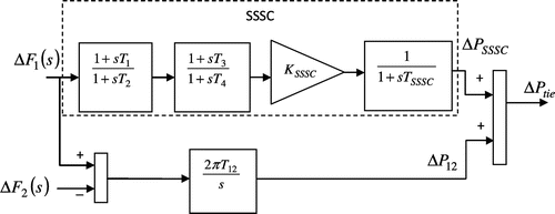
Figure 3. Structure of SSSC as a frequency controller.

Figure 3. Structure of SSSC as a frequency controller.

Figure 4. A schematic diagram of a two area interconnected power system with TCPS in series with tie-line.

Figure 4. A schematic diagram of a two area interconnected power system with TCPS in series with tie-line.

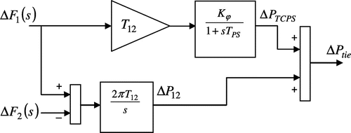
Figure 5. Structure of TCPS as frequency stabilizer.

Figure 5. Structure of TCPS as frequency stabilizer.

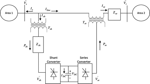
Figure 6. Schematic diagram of two area interconnected power system with UPFC.

Figure 6. Schematic diagram of two area interconnected power system with UPFC.

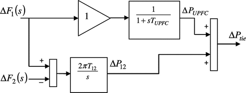
Figure 7. Structure of UPFC as frequency stabilizer.

Figure 7. Structure of UPFC as frequency stabilizer.

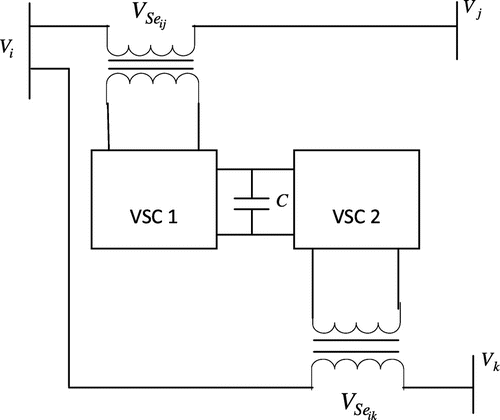
Figure 8. Schematic diagram of IPFC.

Figure 8. Schematic diagram of IPFC.

Figure 9. Structure of IPFC as a frequency controller.

Figure 9. Structure of IPFC as a frequency controller.

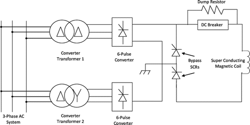
Figure 10. SMES circuit diagram.

Figure 10. SMES circuit diagram.

Figure 11. Structure of SMES as frequency stabilizer.

Figure 11. Structure of SMES as frequency stabilizer.

Figure 12. Structure of Fuzzy PID controller.

Figure 12. Structure of Fuzzy PID controller.

Figure 13. Membership function for the two inputs and two outputs with gains of −1 to 1 and −10 to 10, respectively.
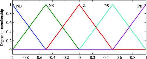
Figure 13. Membership function for the two inputs and two outputs with gains of −1 to 1 and −10 to 10, respectively.

Table 1. Fuzzy rules for the inputs and outputs

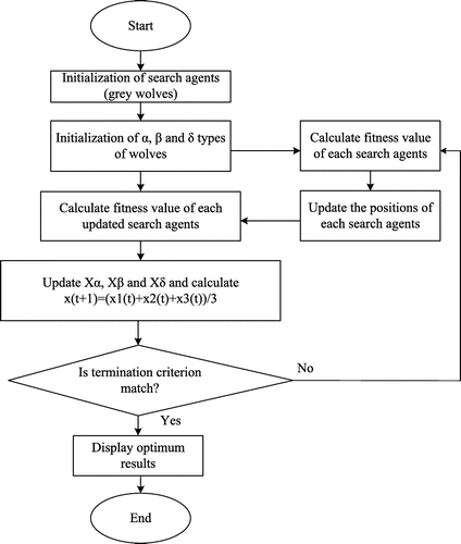
Figure 14. Flowchart of Grey Wolf Optimizer (GWO) algorithm.

Figure 14. Flowchart of Grey Wolf Optimizer (GWO) algorithm.

Table 2. GWO optimized Fuzzy PID controller parameters of power system-1 without physical constraints

Figure 15. (a) Frequency deviation in Area 1 subjected to a step load change of 0.01 p.u. in Area 1, (b) Frequency deviation in Area 2 subjected to a step load change of 0.01 p.u. in Area 1 and (c) Tie-line power flow deviation subjected to a step load change of 0.01 p.u. in Area 1.
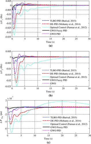
Figure 15. (a) Frequency deviation in Area 1 subjected to a step load change of 0.01 p.u. in Area 1, (b) Frequency deviation in Area 2 subjected to a step load change of 0.01 p.u. in Area 1 and (c) Tie-line power flow deviation subjected to a step load change of 0.01 p.u. in Area 1.

Figure 16. (a) Frequency deviation in Area 1 subjected to a step load change of 0.01 p.u. in Area 1 and their comparison for proposed GWO optimized Fuzzy PID control scheme with TLBO optimized Output feedback SMC scheme, (b) Frequency deviation in Area 2 subjected to a step load change of 0.01 p.u. in Area 1 and their comparison for proposed GWO optimized Fuzzy PID control scheme with TLBO optimized Output feedback SMC scheme and (c) Tie-line power flow deviation subjected to a step load change of 0.01 p.u. in Area 1 and their comparison for proposed GWO optimized Fuzzy PID control scheme with TLBO optimized Output feedback SMC scheme.
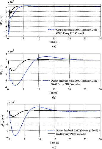
Figure 16. (a) Frequency deviation in Area 1 subjected to a step load change of 0.01 p.u. in Area 1 and their comparison for proposed GWO optimized Fuzzy PID control scheme with TLBO optimized Output feedback SMC scheme, (b) Frequency deviation in Area 2 subjected to a step load change of 0.01 p.u. in Area 1 and their comparison for proposed GWO optimized Fuzzy PID control scheme with TLBO optimized Output feedback SMC scheme and (c) Tie-line power flow deviation subjected to a step load change of 0.01 p.u. in Area 1 and their comparison for proposed GWO optimized Fuzzy PID control scheme with TLBO optimized Output feedback SMC scheme.

Table 3. GWO optimized Fuzzy PID controllers parameters of power system-2 with HVDC link, GRC and reheat turbine

Table 4. Performance evaluation of proposed GWO optimized Fuzzy PID controller by settling time, minimum undershoot and maximum overshoot

Figure 17. (a) Frequency deviation of Area 1 without and with SMES subjected to load change of 0.01 p.u. in Area 1, (b) Frequency deviation of Area 2 without and with SMES subjected to load change of 0.01 p.u. in Area 1 and (c) Tie-line power flow deviation without and with SMES subjected to load change of 0.01 p.u. in Area 1.
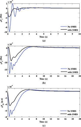
Figure 17. (a) Frequency deviation of Area 1 without and with SMES subjected to load change of 0.01 p.u. in Area 1, (b) Frequency deviation of Area 2 without and with SMES subjected to load change of 0.01 p.u. in Area 1 and (c) Tie-line power flow deviation without and with SMES subjected to load change of 0.01 p.u. in Area 1.

Table 5. System modes, minimum damping ratio, for multi-source multi area power system with HVDC link, GDB, GRC and Reheat turbine without and with SMES

Table 6. Performance evaluation of proposed GWO optimized Fuzzy PID controller by settling time, minimum undershoot and maximum overshoot of multi-source multi area nonlinear power system without and with SMES

Table 7. Optimal gains of controller for different FACTS devices

Figure 18. (a) Frequency deviation of Area 1 with SMES and FACTS subjected to a step load change of 0.01 p.u. in Area 1, (b) Frequency deviation of Area 2 with SMES and FACTS subjected to a step load change of 0.01 p.u. in Area 1 and (c) Tie-line power flow deviation with SMES and FACTS subjected to a step load change of 0.01 p.u. in Area 1.
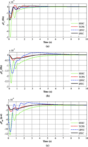
Figure 18. (a) Frequency deviation of Area 1 with SMES and FACTS subjected to a step load change of 0.01 p.u. in Area 1, (b) Frequency deviation of Area 2 with SMES and FACTS subjected to a step load change of 0.01 p.u. in Area 1 and (c) Tie-line power flow deviation with SMES and FACTS subjected to a step load change of 0.01 p.u. in Area 1.

Table 8. Performance criteria for multi-source multi area nonlinear power system with SMES and FACTS

Table 9. System modes, minimum damping ratio, for multi-source multi area nonlinear power system with SMES and FACTS

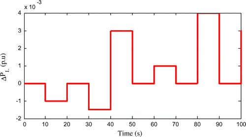
Figure 19. Random load pattern with respect to time.

Figure 19. Random load pattern with respect to time.

Figure 20. (a) Frequency deviation in Area 1 subjected to random load in Area 1 with GWO optimized Fuzzy PID controller, (b) Frequency deviation in Area 2 subjected to random load in Area 1 with GWO optimized Fuzzy PID controller and (c) Tie line power deviation obtained subjected to random load in Area 1 with GWO optimized Fuzzy PID controller.
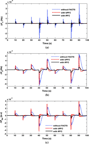
Figure 20. (a) Frequency deviation in Area 1 subjected to random load in Area 1 with GWO optimized Fuzzy PID controller, (b) Frequency deviation in Area 2 subjected to random load in Area 1 with GWO optimized Fuzzy PID controller and (c) Tie line power deviation obtained subjected to random load in Area 1 with GWO optimized Fuzzy PID controller.

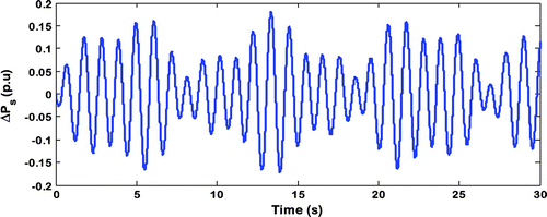
Figure 21. Sinusoidal load pattern with respect to time.

Figure 21. Sinusoidal load pattern with respect to time.

Figure 22. (a) Frequency deviation in Area 1 subjected to sinusoidal load pattern in Area 1 with GWO optimized Fuzzy PID controller with and without FACTS, (b) Frequency deviation in Area 2 subjected to sinusoidal load pattern in Area 1 with GWO optimized Fuzzy PID controller with and without FACTS and (c) Tie line power deviation subjected to sinusoidal load pattern in Area 1 with GWO optimized Fuzzy PID controller with and without FACTS.
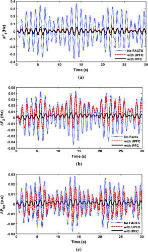
Figure 22. (a) Frequency deviation in Area 1 subjected to sinusoidal load pattern in Area 1 with GWO optimized Fuzzy PID controller with and without FACTS, (b) Frequency deviation in Area 2 subjected to sinusoidal load pattern in Area 1 with GWO optimized Fuzzy PID controller with and without FACTS and (c) Tie line power deviation subjected to sinusoidal load pattern in Area 1 with GWO optimized Fuzzy PID controller with and without FACTS.

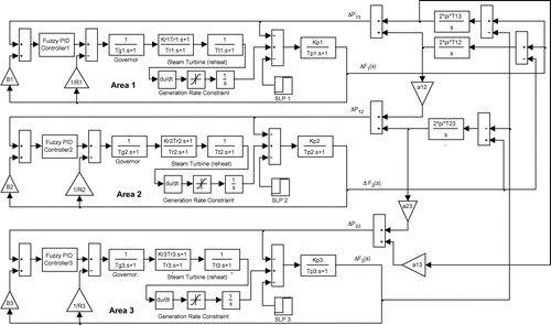
Figure 23. Transfer function model of interconnected three area thermal power system.

Figure 23. Transfer function model of interconnected three area thermal power system.

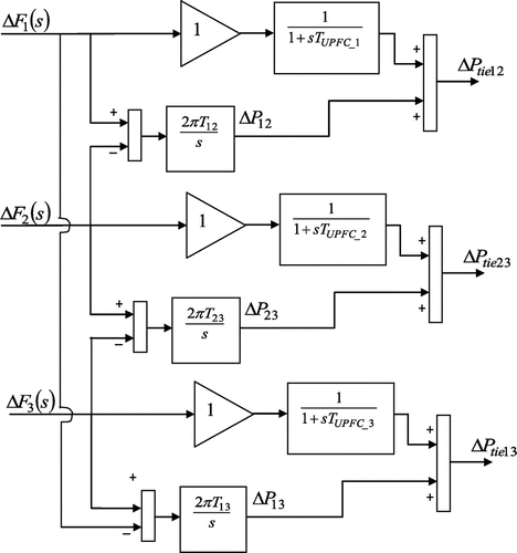
Figure 24. Structure of UPFC as frequency stabilizer for three area power system.

Figure 24. Structure of UPFC as frequency stabilizer for three area power system.

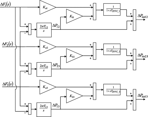
Figure 25. Structure of IPFC as frequency stabilizer for three area power system.

Figure 25. Structure of IPFC as frequency stabilizer for three area power system.

Table 10. Optimal gains of controller for different FACTS devices for three area thermal power system

Figure 26. (a) Frequency deviation in Area 1 subjected to SLP of 1% in Area 1 with GWO optimized Fuzzy PID controller with and without FACTS, (b) Frequency deviation in Area 2 subjected to SLP of 1% in Area 1 with GWO optimized Fuzzy PID controller with and without FACTS and (c) Frequency deviation in Area 3 subjected to SLP of 1% in Area 1 with GWO optimized Fuzzy PID controller with and without FACTS.
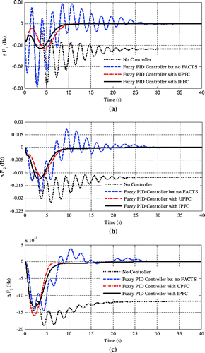
Figure 26. (a) Frequency deviation in Area 1 subjected to SLP of 1% in Area 1 with GWO optimized Fuzzy PID controller with and without FACTS, (b) Frequency deviation in Area 2 subjected to SLP of 1% in Area 1 with GWO optimized Fuzzy PID controller with and without FACTS and (c) Frequency deviation in Area 3 subjected to SLP of 1% in Area 1 with GWO optimized Fuzzy PID controller with and without FACTS.