6,076
Views
23
CrossRef citations to date
0
Altmetric
Research Article

Selection criteria of dc-dc converter and control variable for MPPT of PV system utilized in heating and cooking applications

, ORCID Icon & | (Reviewing Editor)
Article: 1363357 | Received 08 May 2017, Accepted 30 Jul 2017, Published online: 16 Aug 2017

Figures & data

Table 1. Uses of PV panel in rural areas

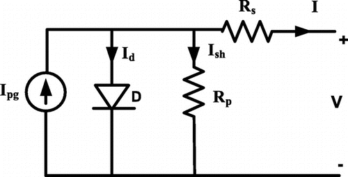
Figure 1. PV panel equivalent circuit.

Figure 1. PV panel equivalent circuit.

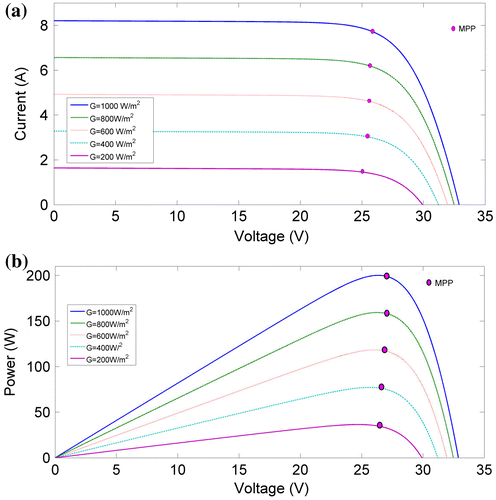
Figure 2. (a) I–V curve and (b) P–V curve of PV module at different irradiation at 25°C.

Figure 2. (a) I–V curve and (b) P–V curve of PV module at different irradiation at 25°C.

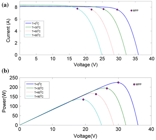
Figure 3. (a) I–V curve and (b) P–V curve of PV module at different temperature at 1,000 W/m2.

Figure 3. (a) I–V curve and (b) P–V curve of PV module at different temperature at 1,000 W/m2.

Table 2. Parameters of Kyocera KC200GT PV panel at STC

Table 3. Selection of converter with respect to battery voltage for MPPT

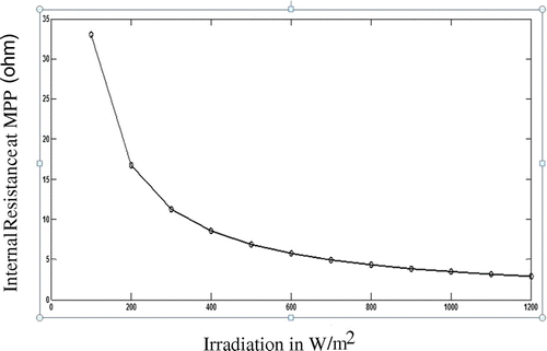
Figure 4. Internal resistance of PV module at MPP at different irradiation.

Figure 4. Internal resistance of PV module at MPP at different irradiation.

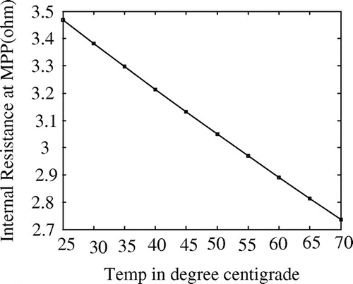
Figure 5. Internal resistance of PV module at MPP at different temperature.

Figure 5. Internal resistance of PV module at MPP at different temperature.

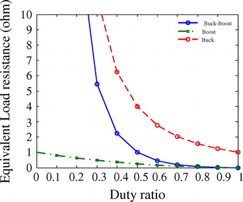
Figure 6. Equivalent load resistance of different types of dc-dc converter with duty ratio.

Figure 6. Equivalent load resistance of different types of dc-dc converter with duty ratio.

Table 4. Selection of converter based on internal resistance of PV panel for MPPT

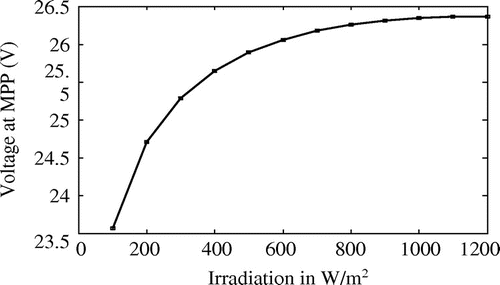
Figure 7. Variation of PV voltage at MPP with insolation.

Figure 7. Variation of PV voltage at MPP with insolation.

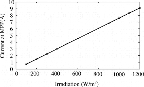
Figure 8. Variation of PV current at MPP with insolation.

Figure 8. Variation of PV current at MPP with insolation.

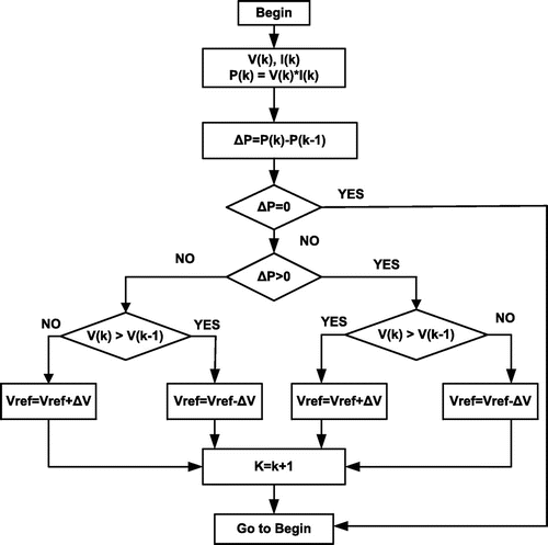
Figure 9. Flowchart of P&O algorithm.

Figure 9. Flowchart of P&O algorithm.

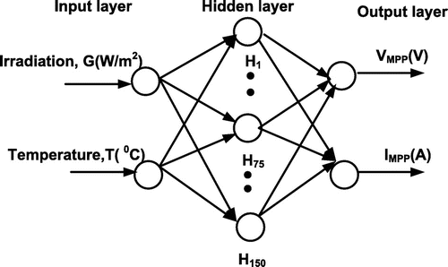
Figure 10. Schematic diagram of the utilized neural network.

Figure 10. Schematic diagram of the utilized neural network.

Figure 11. Unmasked simulation diagram of neural network.

Figure 11. Unmasked simulation diagram of neural network.

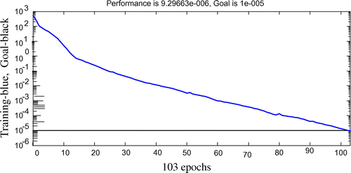
Figure 12. Training of neural network.

Figure 12. Training of neural network.

Table 5. MPP parameter of the KC200GT PV panel at different irradiation

Figure 13. Block diagram of simulation model.

Figure 13. Block diagram of simulation model.

Figure 14. Block diagram of control unit using hysteresis band controller for generation of pulse.

Figure 14. Block diagram of control unit using hysteresis band controller for generation of pulse.

Figure 15. MPPT using P&O algorithm with IMPP as control variable.

Figure 15. MPPT using P&O algorithm with IMPP as control variable.

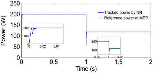
Figure 16. MPPT using NN controller with IMPP as control variable.

Figure 16. MPPT using NN controller with IMPP as control variable.

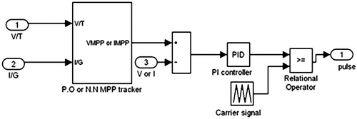
Figure 17. Block diagram of control unit using fixed gain controller for generation of pulse.

Figure 17. Block diagram of control unit using fixed gain controller for generation of pulse.

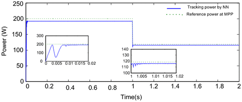
Figure 18. MPPT using NN controller with VMPP as control variable.

Figure 18. MPPT using NN controller with VMPP as control variable.

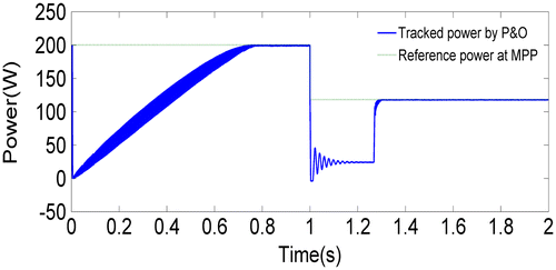
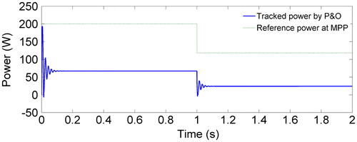
Figure 19. MPPT using P&O algorithm with VMPP as control variable.

Figure 19. MPPT using P&O algorithm with VMPP as control variable.

Table 6. Comparative analysis for both the MPPT controller