1,955
Views
8
CrossRef citations to date
0
Altmetric
Research Article

Displacement-based seismic assessment of masonry buildings for global and local failure mechanisms

ORCID Icon & | (Reviewing Editor)
Article: 1414576 | Received 24 Jul 2017, Accepted 05 Dec 2017, Published online: 18 Dec 2017

Figures & data

Figure 1. Global failure mechanisms of masonry structures.
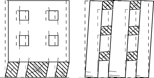
Notes: From left to right: Storey mechanism in case of strong spandrels and weak piers and spandrel mechanism in case of strong piers and weak spandrels (Penna, Citation2005).
Figure 1. Global failure mechanisms of masonry structures.

Figure 2. Observed out-of-plane failure modes for masonry structures (D’Ayala & Speranza, Citation2003).
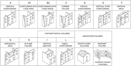
Figure 2. Observed out-of-plane failure modes for masonry structures (D’Ayala & Speranza, Citation2003).

Figure 3. Damage mechanisms of rubble stone masonry.
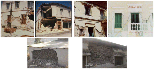
Notes: From left to right and top to bottom: Coupled in-plane/out-of-plane damage of structures during 1995 Aegion earthquake in Greece (Penna, Citation2005), in-plane shear damage of field stone masonry during 1999 Athens earthquake in Greece (Tassios & Syrmakezis, Citation2002), and out-of-plane delamination failure mode for masonry structures (Javed, Citation2008).
Figure 3. Damage mechanisms of rubble stone masonry.

Figure 4. Graphical representation of DBELA.
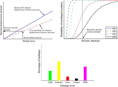
Notes: From left to right and top to bottom: Idealized displacement response spectrum and the limit state overdamping, analytical seismic fragility functions and damage scenario, where DS represents different damage state of structures on regional scale.
Figure 4. Graphical representation of DBELA.

Figure 5. Nonlinear static SDOF idealization and capacity curve, mechanical model, for global mechanism.

Figure 5. Nonlinear static SDOF idealization and capacity curve, mechanical model, for global mechanism.

Figure 6. Nonlinear static SDOF idealization, mechanical model, of masonry wall for out-of-plane failure modes, after Doherty et al. (Citation2002).

Figure 6. Nonlinear static SDOF idealization, mechanical model, of masonry wall for out-of-plane failure modes, after Doherty et al. (Citation2002).

Figure 7. Flow chart for the derivation of vector-based displacement-based fragility functions, global mechanism.
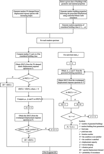
Figure 7. Flow chart for the derivation of vector-based displacement-based fragility functions, global mechanism.

Figure 8. Flow chart for the derivation of vector-based displacement-based fragility functions, local mechanism.
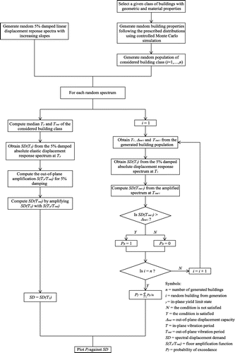
Figure 8. Flow chart for the derivation of vector-based displacement-based fragility functions, local mechanism.

Figure 9. Definition of seismic demand on the out-of-plane walls.
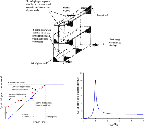
Notes: From top to bottom and left to right: load path for out-of-plane walls, absolute spectrum to define floor absolute displacement demand and out-of-plane amplification spectrum.
Figure 9. Definition of seismic demand on the out-of-plane walls.

Figure 10. Equivalent frame method.

Notes: From left to right: equivalent frame idealization of masonry structural wall and Nonlinear force-displacement response of frame element, considering either multilinear or bilinear behavior.
Figure 10. Equivalent frame method.

Figure 11. Lateral force-displacement response of case study masonry walls.
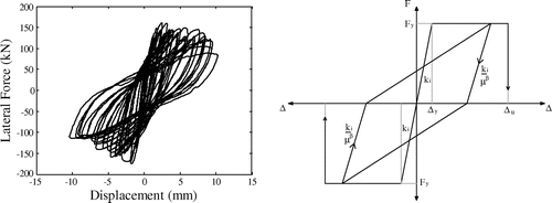
Notes: From left to right: experimentally obtained response through quasi-static cyclic test on full scale wall (Javed, Citation2008) and simplified used in the present study.
Figure 11. Lateral force-displacement response of case study masonry walls.

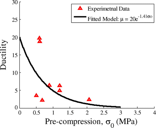
Figure 12. Ductility capacity model for masonry walls.

Figure 12. Ductility capacity model for masonry walls.

Figure 13. Validation of the proposed modelling hypothesis for masonry structure, tested at the University of Pavia (Magenes et al., Citation1995).

Notes: From left to right: equivalent capacity curve and ultimate damage state.
Figure 13. Validation of the proposed modelling hypothesis for masonry structure, tested at the University of Pavia (Magenes et al., Citation1995).

Figure 14. The effect of different wall density and floor area on the yield strength, exemplificative chart.
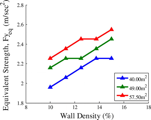
Figure 14. The effect of different wall density and floor area on the yield strength, exemplificative chart.

Table 1. Structural properties considered to generate proto type structural models for masonry structures

Figure 15. Pushover curves for case study two-storey low-rise structures and the derivation of capacity curves parameters.
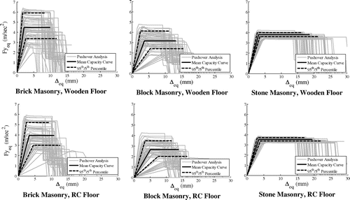
Figure 15. Pushover curves for case study two-storey low-rise structures and the derivation of capacity curves parameters.

Table 2. Capacity curve parameters (median, lower and upper bound) for case study masonry structures

Figure 16. Mean spectrum of the selected accelerograms and comparison with the EC8 Type I-C soil spectrum.
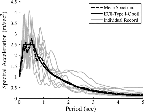
Figure 16. Mean spectrum of the selected accelerograms and comparison with the EC8 Type I-C soil spectrum.

Table 3. Drift limits computed for case study masonry structures, in percent

Figure 17. Collapse multiplier for typical out-of-plane failure of façade walls obtained experimentally (Restrepo-Velez & Magenes, Citation2009).
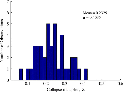
Figure 17. Collapse multiplier for typical out-of-plane failure of façade walls obtained experimentally (Restrepo-Velez & Magenes, Citation2009).

Table 4. Parameters used in the random generation of structures for fragility functions derivation for South-Asia countries

Figure 18. Vector-based fragility functions for case study masonry structures.
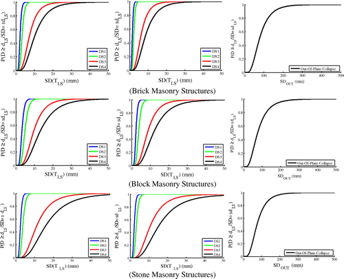
Notes: From left to right: masonry structures with rc floors (in-plane mechanism), wooden floors (in-plane mechanism) and wooden floors (out-of-plane mechanism).
Figure 18. Vector-based fragility functions for case study masonry structures.

Figure 19. Scalar-based, SA (0.30 s), fragility functions for case study masonry structures.
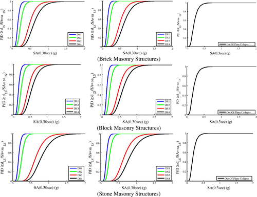
Notes: From left to right: masonry structures with rc floors (in-plane mechanism), wooden floors (in-plane mechanism) and wooden floors (out-of-plane mechanism).
Figure 19. Scalar-based, SA (0.30 s), fragility functions for case study masonry structures.

Figure 20. Scalar-based, PGA, fragility functions for case study masonry structures.
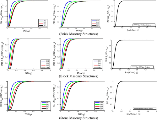
Notes: From left to right: masonry structures with rc floors (in-plane mechanism), wooden floors (in-plane mechanism) and wooden floors (out-of-plane mechanism).
Figure 20. Scalar-based, PGA, fragility functions for case study masonry structures.

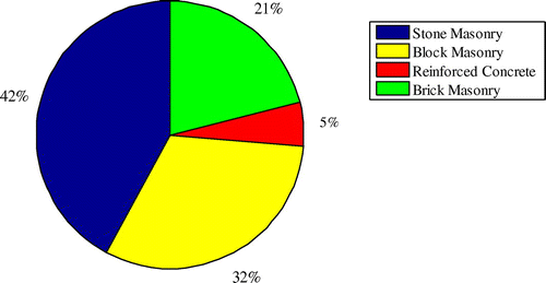
Figure 21. Percentage of structure typology to total stock subjected to 2005 Kashmir earthquake.

Figure 21. Percentage of structure typology to total stock subjected to 2005 Kashmir earthquake.

Figure 22. Percentage of structures damaged during 2005 Kashmir earthquake.
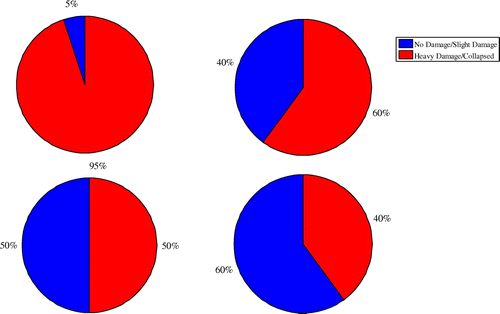
Notes: From left to right and top to bottom: stone masonry structures, block masonry structures, reinforced concrete structures and brick masonry structures.
Figure 22. Percentage of structures damaged during 2005 Kashmir earthquake.

Table 5. Input parameters for vector-based (inelastic spectral displacement) fragility functions, lognormal distribution is conservatively considered

Table 6. Input parameters for scalar-based (elastic spectral acceleration), SA (0.30 s), fragility functions, lognormal distribution is conservatively considered

Table 7. Input parameters for scalar-based (peak ground acceleration) fragility functions, lognormal distribution is conservatively considered

Figure 23. Test and validation of the UPAV methodology against the 2005 Kashmir earthquake.
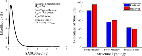
Notes: From left to right: the likelihood of randomly generated ground motions in the affected areas and the percentage of structures heavily damaged/collapsed (mean estimate).
Figure 23. Test and validation of the UPAV methodology against the 2005 Kashmir earthquake.