1,266
Views
20
CrossRef citations to date
0
Altmetric
Research Article

Optimal design of PD-Fuzzy-PID cascaded controller for automatic generation control

ORCID Icon, & | (Reviewing Editor)
Article: 1416535 | Received 14 Aug 2017, Accepted 08 Dec 2017, Published online: 25 Dec 2017

Figures & data

Figure 1. The hybrid-source power system model (Sahu et al., Citation2016) represented by transfer functions.
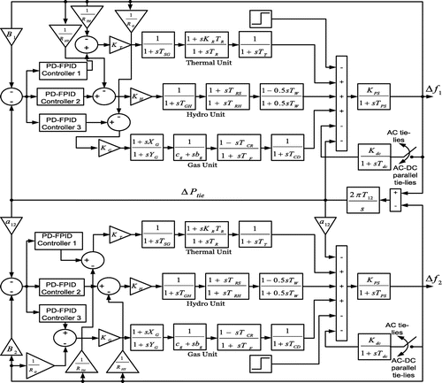
Figure 1. The hybrid-source power system model (Sahu et al., Citation2016) represented by transfer functions.

Figure 2. Structure of cascaded PD-Fuzzy-PID controller.

Figure 2. Structure of cascaded PD-Fuzzy-PID controller.

Figure 3. Triangular membership functions for the fuzzy controller.

Figure 3. Triangular membership functions for the fuzzy controller.

Table 1. Fuzzy Rule-base of fuzzy inference system

Figure 4. Convergence behaviour of different optimization techniques.

Figure 4. Convergence behaviour of different optimization techniques.

Figure 5. Deviation of frequency in Aea 1 and Area 2 without any controller.

Figure 5. Deviation of frequency in Aea 1 and Area 2 without any controller.

Table 2. Scaling parameters of different controllers with AC link only

Figure 6(a). Deviation of frequency in area 1 due to 1% SLP in area 1 with AC line only.

Figure 6(a). Deviation of frequency in area 1 due to 1% SLP in area 1 with AC line only.

Figure 6(b). Deviation of frequency in area 2 due to 1% SLP in area 1 with AC line only.

Figure 6(b). Deviation of frequency in area 2 due to 1% SLP in area 1 with AC line only.

Figure 6(c). Deviation of tie-line power due to 1% SLP in area 1 with AC line only.

Figure 6(c). Deviation of tie-line power due to 1% SLP in area 1 with AC line only.

Table 3. Settling time, peak overshoots and undershoots of the response considering AC tie-lines only

Figure 7(a). Bar plot of settling time with AC tie-line only.

Figure 7(a). Bar plot of settling time with AC tie-line only.

Figure 7(b). Bar plot of peak overshoot with AC tie-line only.

Figure 7(b). Bar plot of peak overshoot with AC tie-line only.

Figure 7(c). Bar plot of peak undershoot with AC tie-line only.

Figure 7(c). Bar plot of peak undershoot with AC tie-line only.

Table 4. Percentage improvement in settling time, peak overshoots and under shoots with AC tie-lines only

Figure 8. Block diagram of two area system connected by HVAC and HVDC tie-line.

Figure 8. Block diagram of two area system connected by HVAC and HVDC tie-line.

Table 5. Scaling parameters of different controllers with HVDC link

Figure 9(a). Deviation of frequency in area 1 due to 1% SLP in area 1 with AC-DC tie-lines.

Figure 9(a). Deviation of frequency in area 1 due to 1% SLP in area 1 with AC-DC tie-lines.

Figure 9(b). Deviation of frequency in area 2 due to 1% SLP in area 1 with AC-DC tie-lines.

Figure 9(b). Deviation of frequency in area 2 due to 1% SLP in area 1 with AC-DC tie-lines.

Figure 9(c). Deviation of tie-line power due to 1% SLP in area 1 with AC-DC tie-lines.

Figure 9(c). Deviation of tie-line power due to 1% SLP in area 1 with AC-DC tie-lines.

Table 6. Settling time, peak overshoots and undershoots of the response considering AC-DC tie-line

Table 7. Percentage improvement in settling time, peak overshoots and undershoots with HVDC link

Figure 10. Deviation of frequency in area 1 due to change of SLP in area 1 with Ac tie-line only.

Figure 10. Deviation of frequency in area 1 due to change of SLP in area 1 with Ac tie-line only.

Figure 11. Deviation of frequency of area 1 due to parameter variations with Ac tie-line only.

Figure 11. Deviation of frequency of area 1 due to parameter variations with Ac tie-line only.

Table 8. Variations of settling time, peak overshoots and undershoots due to parameter variations

Figure 12(a). Random loading pattern for area 1 considering AC tie-line only.

Figure 12(a). Random loading pattern for area 1 considering AC tie-line only.

Figure 12(b). Deviation of frequency of area 1 due to random loading.

Figure 12(b). Deviation of frequency of area 1 due to random loading.

Figure 12(c). Deviation of frequency of area 2 due to random loading.

Figure 12(c). Deviation of frequency of area 2 due to random loading.

Figure 12(d). Deviation of tie-line power due to random loading.

Figure 12(d). Deviation of tie-line power due to random loading.

Table 9. The value of various performance indices

Figure 13(a). Connection of UPFC in a two area system.

Figure 13(a). Connection of UPFC in a two area system.

Figure 13(b). Deviation of frequency of area 1 with UPFC and AC tie-line.

Figure 13(b). Deviation of frequency of area 1 with UPFC and AC tie-line.

Figure 13(c). Deviation of frequency of area 1 with UPFC and AC-DC tie-line.

Figure 13(c). Deviation of frequency of area 1 with UPFC and AC-DC tie-line.