3,660
Views
8
CrossRef citations to date
0
Altmetric
Review Article

Hydrodynamics of three phase flow in upstream pipes

ORCID Icon, & | (Reviewing Editor)
Article: 1433983 | Received 21 Sep 2017, Accepted 16 Jan 2018, Published online: 28 Feb 2018

Figures & data

Figure 1. CSIRO gamma-ray MFM where P and T are pressure and temperature transducers, respectively by Roach and Watt (Citation1997).
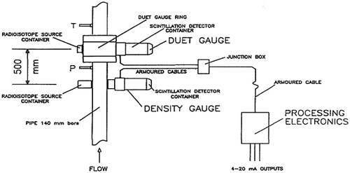
Figure 1. CSIRO gamma-ray MFM where P and T are pressure and temperature transducers, respectively by Roach and Watt (Citation1997).

Figure 2. Three phase flow system schematic by Karami et al. (Citation2015).
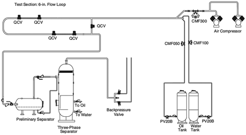
Figure 2. Three phase flow system schematic by Karami et al. (Citation2015).

Figure 3. Equation symbols as they relate to three phase flow by Neogi et al. (Citation1994).

Figure 3. Equation symbols as they relate to three phase flow by Neogi et al. (Citation1994).

Figure 4. Liquid height, h l, and water height, h w, for the gas-oil-water (G-O-W) system Taitel et al. (Citation1995).
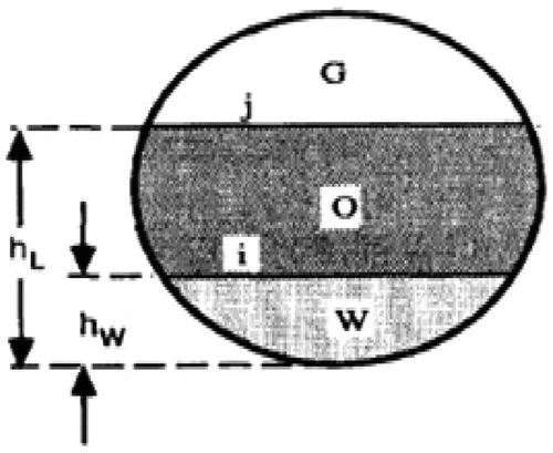
Figure 4. Liquid height, h l, and water height, h w, for the gas-oil-water (G-O-W) system Taitel et al. (Citation1995).

Figure 5. Staggered grid used for discretization by Soprano et al. (Citation2012).
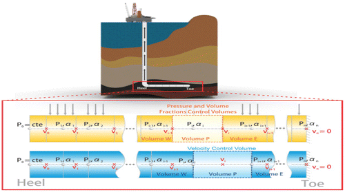
Figure 5. Staggered grid used for discretization by Soprano et al. (Citation2012).

Figure 6. Jacobian matrix by Soprano et al. (Citation2012).
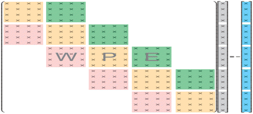
Figure 6. Jacobian matrix by Soprano et al. (Citation2012).

Table 1. Block components of the Jacobian matrix by Soprano et al. (Citation2012)

Figure 7. Schematic of flow system by Lee et al. (Citation1993).
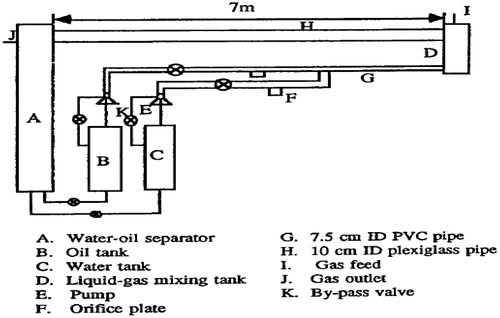
Figure 7. Schematic of flow system by Lee et al. (Citation1993).

Figure 8. Three phase flow regimes observed by Lee et al. (Citation1993).
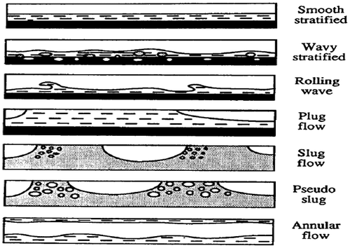
Figure 8. Three phase flow regimes observed by Lee et al. (Citation1993).

Figure 9. Flow pattern map for 50% LVT200 oil- 50% water in the presence of carbon dioxide gas by Lee et al. (Citation1993).
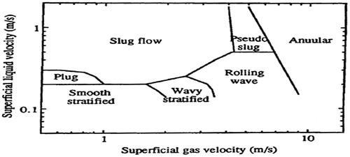
Figure 9. Flow pattern map for 50% LVT200 oil- 50% water in the presence of carbon dioxide gas by Lee et al. (Citation1993).

Figure 10. Effect of water cut in LVT200 oil on flow regime transitions by Lee et al. (Citation1993).
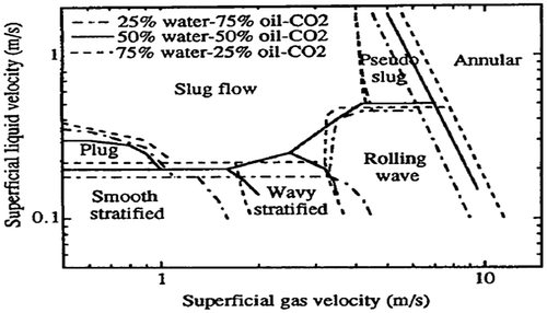
Figure 10. Effect of water cut in LVT200 oil on flow regime transitions by Lee et al. (Citation1993).

Figure 11. Effect of water cut in Arcopak90 oil on flow regime transitions by Lee et al. (Citation1993).
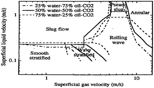
Figure 11. Effect of water cut in Arcopak90 oil on flow regime transitions by Lee et al. (Citation1993).

Table 2. Flow regime regions identified by Açikgöz et al. (Citation1992)

Figure 12. Oil-based dispersed plug flow (region 1 according to Table ) by Açikgöz et al. (Citation1992).
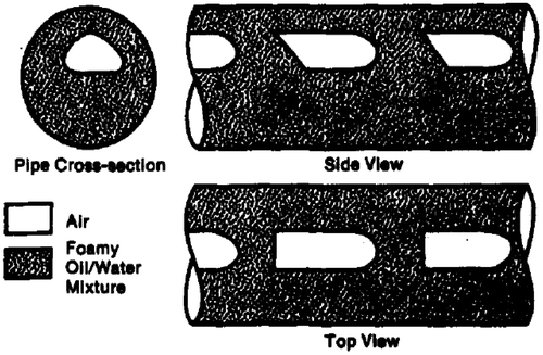
Figure 12. Oil-based dispersed plug flow (region 1 according to Table 2) by Açikgöz et al. (Citation1992).

Figure 13. Oil-based dispersed slug flow (region 2 according to Table ) by Açikgöz et al. (Citation1992).
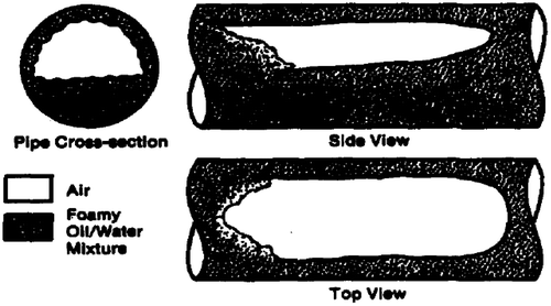
Figure 13. Oil-based dispersed slug flow (region 2 according to Table 2) by Açikgöz et al. (Citation1992).

Figure 14. Oil-based dispersed stratified/wavy flow (region 3 according to Table ) by Açikgöz et al. (Citation1992).
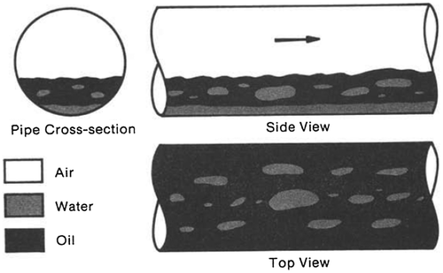
Figure 14. Oil-based dispersed stratified/wavy flow (region 3 according to Table 2) by Açikgöz et al. (Citation1992).

Figure 15. Oil-based separated stratified/wavy flow (region 4 according to Table ) by Açikgöz et al. (Citation1992).
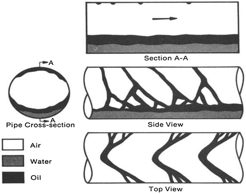
Figure 15. Oil-based separated stratified/wavy flow (region 4 according to Table 2) by Açikgöz et al. (Citation1992).

Figure 16. Oil-based separated wavy stratifying annular-flow (region 5 according to Table ) by Açikgöz et al. (Citation1992).
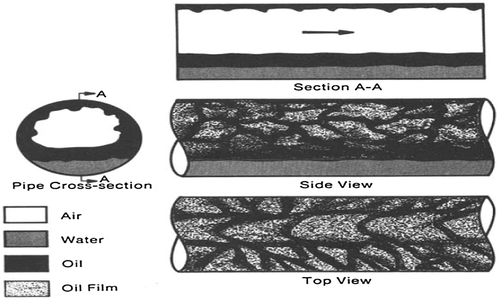
Figure 16. Oil-based separated wavy stratifying annular-flow (region 5 according to Table 2) by Açikgöz et al. (Citation1992).

Figure 17. Oil-based separated/dispersed stratifying-annular flow (region 6 according to Table ) by Açikgöz et al. (Citation1992).
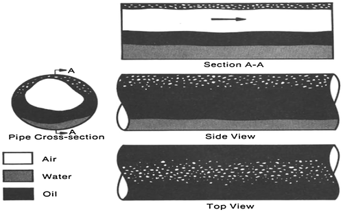
Figure 17. Oil-based separated/dispersed stratifying-annular flow (region 6 according to Table 2) by Açikgöz et al. (Citation1992).

Figure 18. Water-based dispersed slug flow (region 7 according to Table ) by Açikgöz et al. (Citation1992).
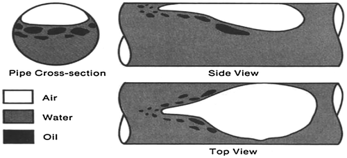
Figure 18. Water-based dispersed slug flow (region 7 according to Table 2) by Açikgöz et al. (Citation1992).

Figure 19. Water-based dispersed stratified/wavy flow (region 8 according to Table ) by Açikgöz et al. (Citation1992).
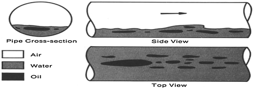
Figure 19. Water-based dispersed stratified/wavy flow (region 8 according to Table 2) by Açikgöz et al. (Citation1992).

Figure 20. Water-based separated dispersed incipient stratifying-annular flow (region 9 according to Table ) by Açikgöz et al. (Citation1992).
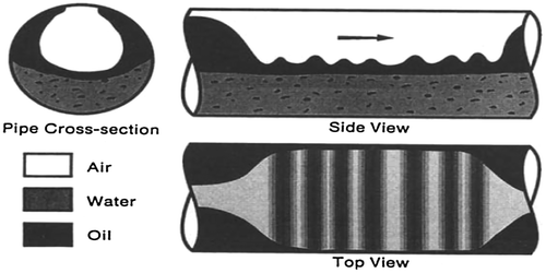
Figure 20. Water-based separated dispersed incipient stratifying-annular flow (region 9 according to Table 2) by Açikgöz et al. (Citation1992).

Figure 21. Water-based dispersed stratifying-annular flow (region 10 according to Table ) by Açikgöz et al. (Citation1992).
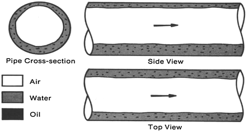
Figure 21. Water-based dispersed stratifying-annular flow (region 10 according to Table 2) by Açikgöz et al. (Citation1992).

Figure 22. Inclinable flow loop system by Wilkens and Jepson (Citation1996).
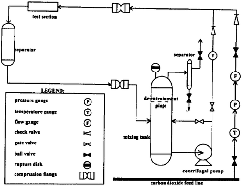
Figure 22. Inclinable flow loop system by Wilkens and Jepson (Citation1996).

Figure 23. Oil-dominated flow regimes 1–4 by Woods et al. (Citation1998).
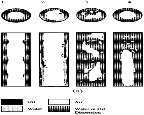
Figure 23. Oil-dominated flow regimes 1–4 by Woods et al. (Citation1998).

Figure 24. Water-dominated flow regimes 5–8 by Woods et al. (Citation1998).
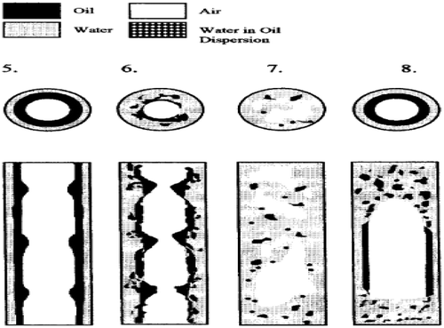
Figure 24. Water-dominated flow regimes 5–8 by Woods et al. (Citation1998).

Figure 25. Graph for pressure drop varying with water cut by Shi et al. (Citation1999).
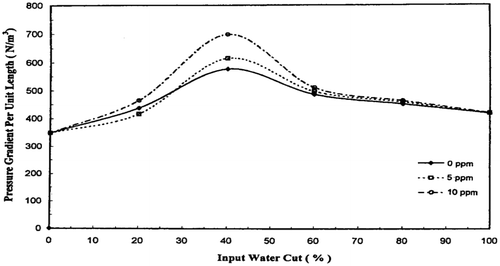
Figure 25. Graph for pressure drop varying with water cut by Shi et al. (Citation1999).