Figures & data
Figure 1. The flow chart of the study stages.
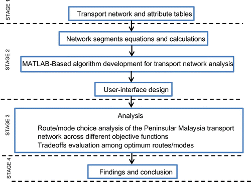
Figure 2. Highway (a), federal road (b), railroad (c), and waterway (d).
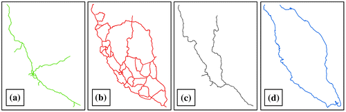
Figure 3. Examples of artificial lines.
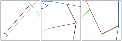
Figure 4. Ports (left) and intermodal terminals (right).
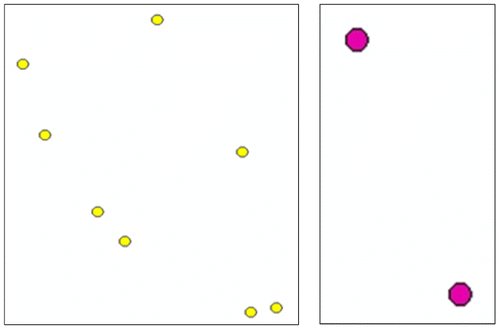
Figure 5. Intermodal transport network of Peninsular Malaysia.
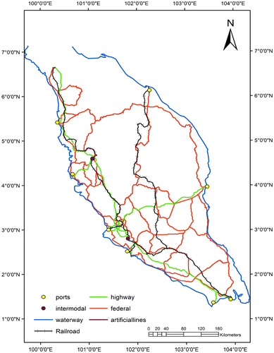
Table 1. Associated emission factor for different transport modes
Figure 6. Main window of the user-interface.
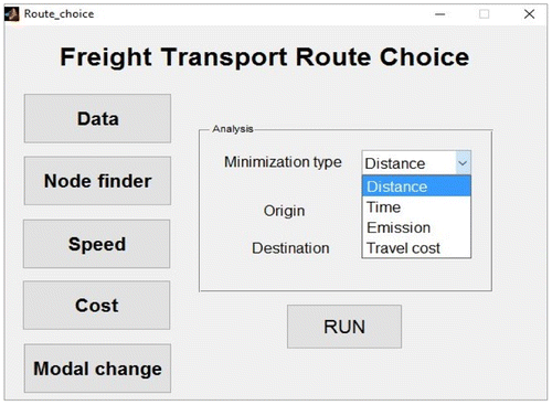
Figure 7. Node number of the origin point.
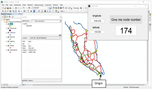
Figure 8. Node number of the destination point.
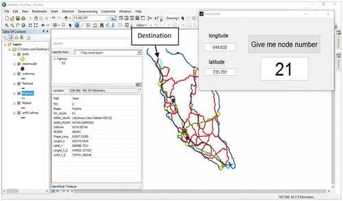
Figure 9. Network representation of distance analysis.
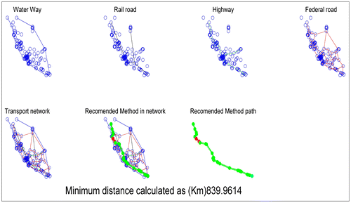
Figure 10. Graphical representation of distance analysis.

Figure 11. Network representation of time analysis.
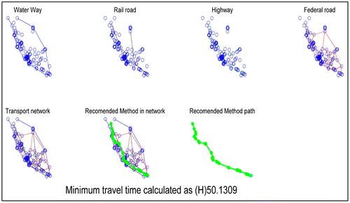
Figure 12. Graphical representation of time analysis.
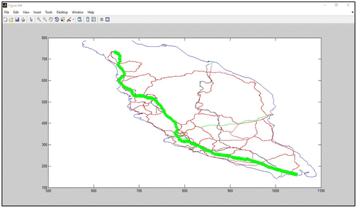
Figure 13. Network representation of emission analysis.
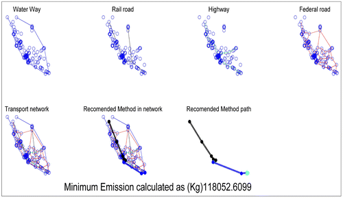
Figure 14 Graphical representation of emission analysis.
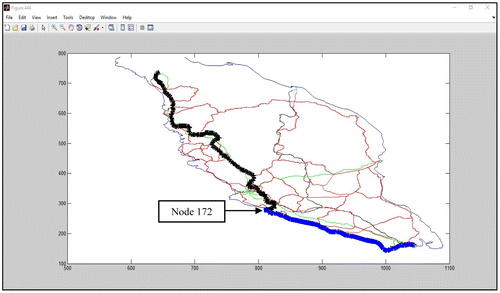
Figure 15. Values for influential parameters on transport cost.
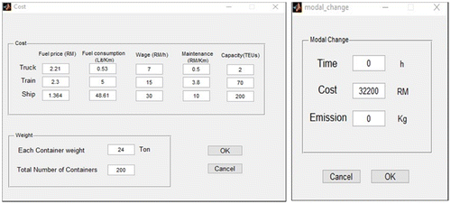
Figure 16. Network representation of transport cost analysis.
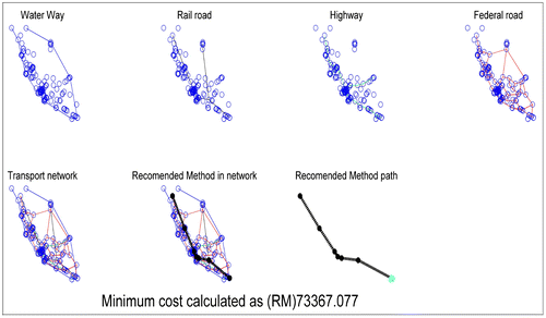
Figure 17. Graphical representation of transport cost analysis.
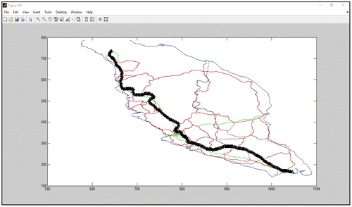
Figure 18. Route analysis result.
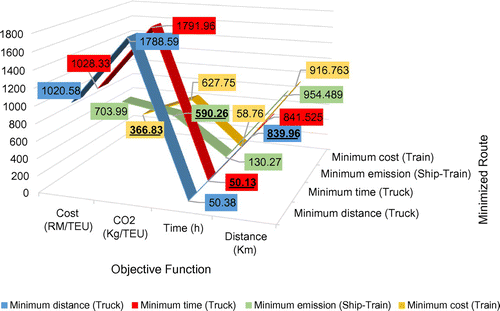
Figure 19. Destination node.
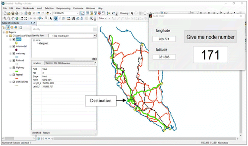
Figure 20. Network and graphical representation of transport distance and time analysis.
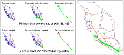
Figure 21. Network and graphical representation of emission and cost analysis.
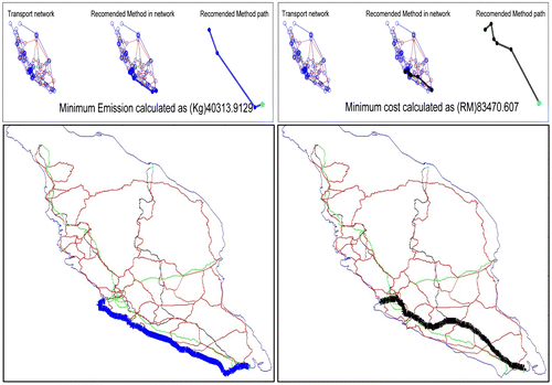
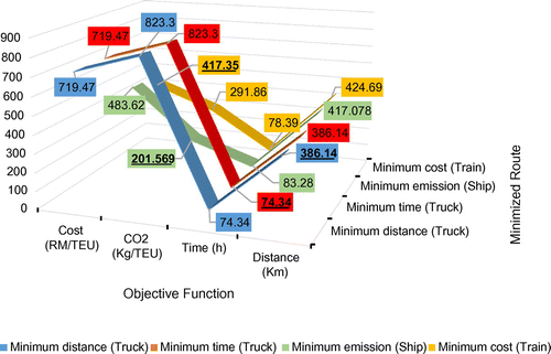
Figure 22. Route analysis result.