5,887
Views
20
CrossRef citations to date
0
Altmetric
Research Article

Synthesis and characterisation of zeolite-A and Zn-exchanged zeolite-A based on natural aluminosilicates and their potential applications

, , , , , & | (Reviewing Editor) show all
Article: 1440480 | Received 14 Sep 2017, Accepted 11 Feb 2018, Published online: 01 Mar 2018

Figures & data

Table 1. Mineralogy and particle size of raw materials

Table 2. Sample designation

Table 3. XRF analyses of raw materials

Figure 1. XRD Pattern for Kaolin and Metakaolin.

Figure 1. XRD Pattern for Kaolin and Metakaolin.

Figure 2. The XRD pattern for the samples crystallized for 3 h (for batch formulations containing bauxite).
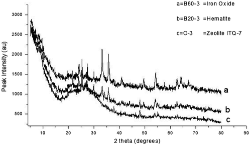
Figure 2. The XRD pattern for the samples crystallized for 3 h (for batch formulations containing bauxite).

Figure 3. XRD pattern of the control experiment with the as-synthesized zeolite varied with bauxite addition.
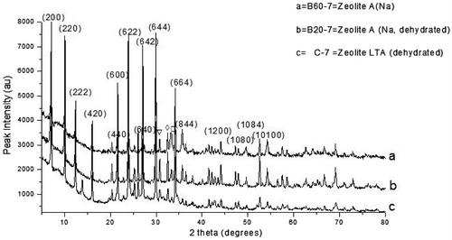
Figure 3. XRD pattern of the control experiment with the as-synthesized zeolite varied with bauxite addition.

Figure 4. XRD pattern of the control experiment with the as-synthesized zeolite varied with feldspar addition.
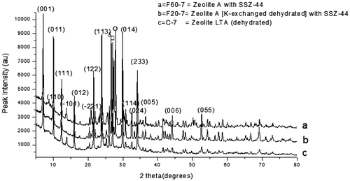
Figure 4. XRD pattern of the control experiment with the as-synthesized zeolite varied with feldspar addition.

Figure 5. XRD pattern of the control experiment with the as-synthesized zeolite varied with raw silica addition.
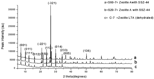
Figure 5. XRD pattern of the control experiment with the as-synthesized zeolite varied with raw silica addition.

Table 4. Process conditions and XRD results of synthetic zeolites

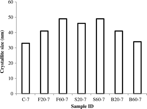
Figure 6. The effect of varying the Si/Al on the crystallite sizes.

Figure 6. The effect of varying the Si/Al on the crystallite sizes.

Figure 7. The FTIR of the control experiment and the synthesized zeolite samples containing 20 wt.% of bauxite, feldspar and silica respectively.
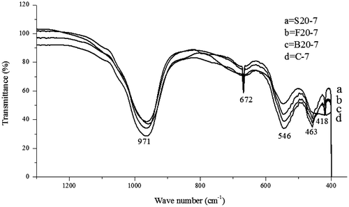
Figure 7. The FTIR of the control experiment and the synthesized zeolite samples containing 20 wt.% of bauxite, feldspar and silica respectively.

Figure 8. The FTIR of the control experiment and the synthesized zeolite samples containing 60 wt.% of bauxite, feldspar and silica, respectively.
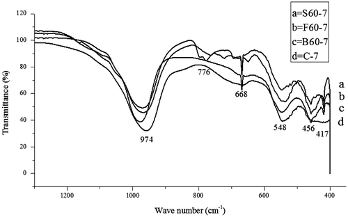
Figure 8. The FTIR of the control experiment and the synthesized zeolite samples containing 60 wt.% of bauxite, feldspar and silica, respectively.

Figure 9. The N2 adsorption/desorption isotherm of synthesized zeolite (Control experiment, C-7) nanoparticles.
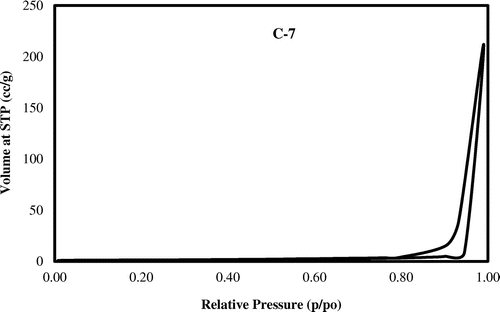
Figure 9. The N2 adsorption/desorption isotherm of synthesized zeolite (Control experiment, C-7) nanoparticles.

Figure 10. SEM of (a) Zeolite A; (b) SEM of Zeolite A formulated with 60% Silica; (c) SEM of Zn exchanged Zeolite A.
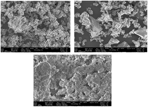
Figure 10. SEM of (a) Zeolite A; (b) SEM of Zeolite A formulated with 60% Silica; (c) SEM of Zn exchanged Zeolite A.
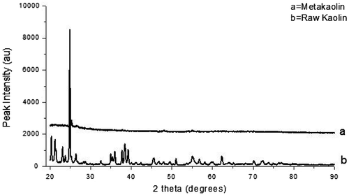
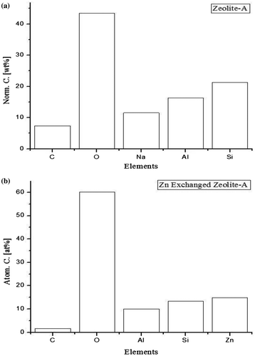
Figure 11. EDX of (a) Zeolite-A; EDX of (b) Zn exchanged Zeolite-A.

Figure 11. EDX of (a) Zeolite-A; EDX of (b) Zn exchanged Zeolite-A.

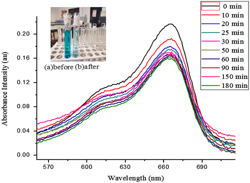
Figure 12. Absorbance intensity curve at various time interval.

Figure 12. Absorbance intensity curve at various time interval.

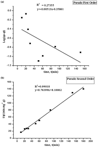
Figure 13. (a) Pseudo first-order; (b) Pseudo second-order.

Figure 13. (a) Pseudo first-order; (b) Pseudo second-order.

Table 5. Parameters of kinetic models of MB adsorption on the adsorbent

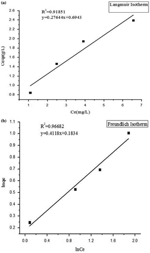
Figure 14. (a) Langmuir Isotherm model; (b) Freundlich Isotherm model.

Figure 14. (a) Langmuir Isotherm model; (b) Freundlich Isotherm model.

Table 6. The adsorption isotherm parameters

Table 7. The regeneration performance of the alkaline treated adsorbent

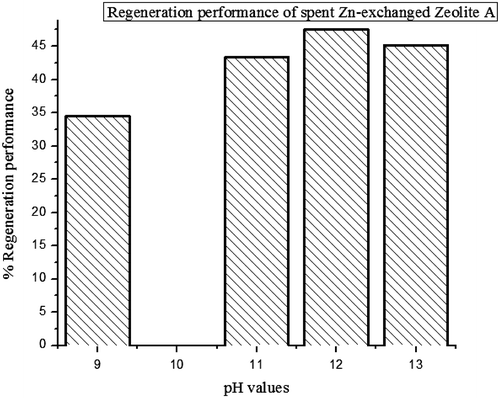
Figure 15. Regeneration of spent Zn-exchanged Zeolite A.

Figure 15. Regeneration of spent Zn-exchanged Zeolite A.