Figures & data
Figure 1. Position of the existing station and target locations.
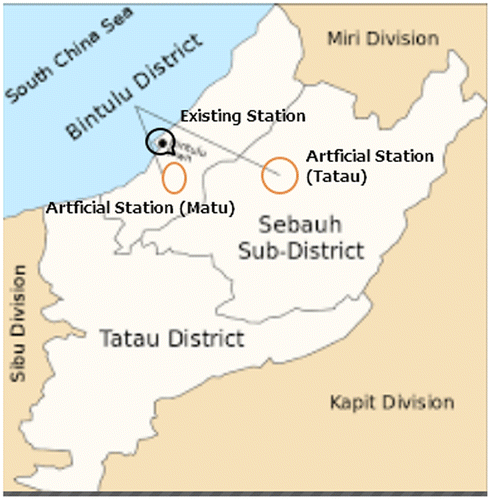
Figure 2. Process of EFFNN development.
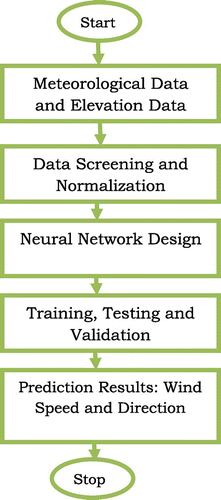
Table 1. PDF and CDF models
Table 2. GOF models
Figure 3. A sample of wind speed map of Sarawak at 20 m.
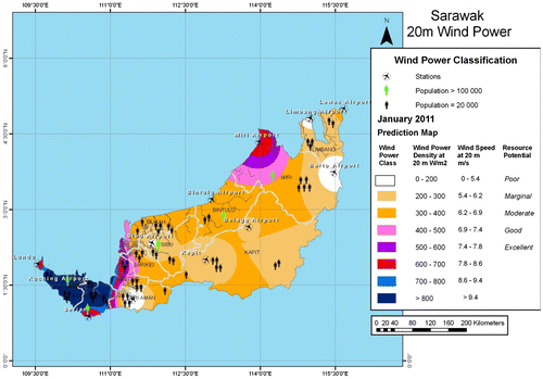
Figure 4. Wind power based on exact and formulated model.
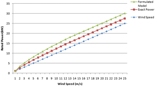
Figure 5. ANN training (a) Matu (b) Tatau.
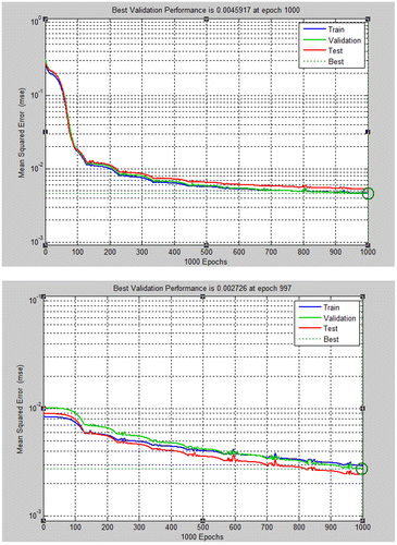
Figure 6. Correlation between ANN and reference based on training data sets for (a) Matu and (b) Tatu.
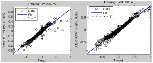
Figure 7. Regression between ANN and reference based on whole training data sets for (a) Matu and (b) Tatu.
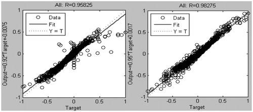
Figure 8. Comparison between predicted and observed monthly wind speed.
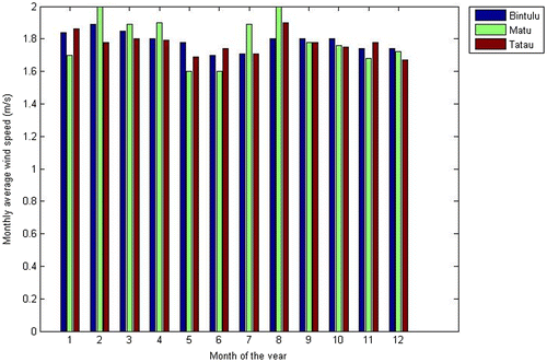
Table 3. Summary of the percentile of missing wind speed values
Table 4. Effectiveness of methods based on station
Figure 9. Variation of daily average wind speed for ten years (2006–2015).
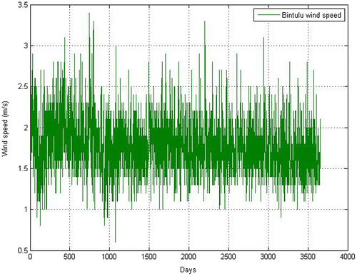
Figure 10. Wind direction for ten years (2006–2015) at Bintulu, Matu, and Tatau.
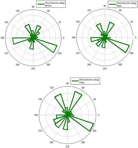
Table 5. Wind speed (2006–2015) at 10–40 m heights in Sibu
Table 6. Comparisons of monthly air densities at different heights (2006–2015) at Sibu
Table 7. GOF summary at Bintulu
Figure 11. Weibull model fitted wind power density.
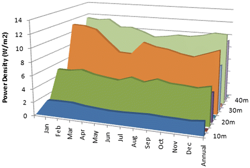
Figure 12. Gamma model fitted wind power density.
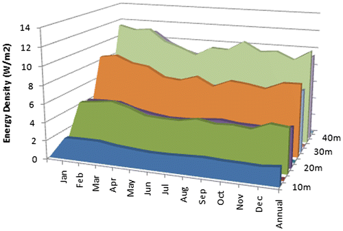
Table 8. Comparisons of wind power density at predicted locations
Table 9. Comparisons of wind energy density at predicted locations
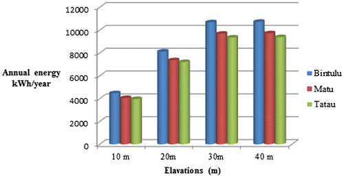
Figure 13. Computed AEO at different elevation.