8,256
Views
2
CrossRef citations to date
0
Altmetric
Research Article

Potential for harvesting electrical energy from swing and revolving door use

& |
Article: 1458435 | Received 16 Nov 2017, Accepted 25 Mar 2018, Published online: 12 Apr 2018

Figures & data

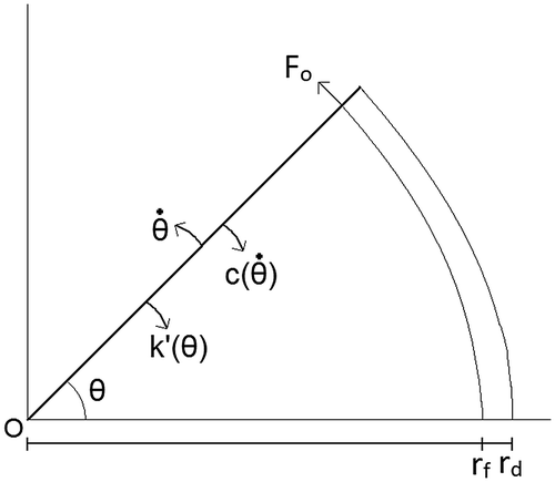
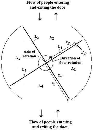
Figure 1. Diagram showing the layout of the door to be modelled.

Figure 1. Diagram showing the layout of the door to be modelled.

Table 1. Boundary conditions used to determine the phase of the swing door’s motion

Table 2. The equations used to model the motion of a simple swing door

Table 3. Equations of motion used to determine the motion of a swing door, utilising method 1 of energy generation

Table 4. Parameters values utilised for baseline calculations

Figure 2. Comparison of the angular position of the door when no generator is present with the three methods of generation.
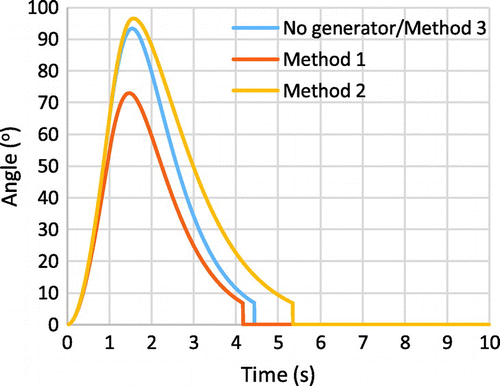
Note: The opening force was applied for 1 s.
Figure 2. Comparison of the angular position of the door when no generator is present with the three methods of generation.

Figure 3. Angular position of the door during a door opening event for method 1. The damping effect of the generator (ξ) on the door is varied. Energy potential available for harvesting from method 1 as a function of the damping effect of the generator.
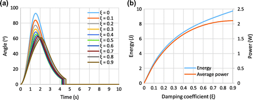
Figure 3. Angular position of the door during a door opening event for method 1. The damping effect of the generator (ξ) on the door is varied. Energy potential available for harvesting from method 1 as a function of the damping effect of the generator.

Figure 4. The angular position of the door using method 2 for varying proportions of the torsional spring constant of springs 1, k1, and 2, k2.

Figure 4. The angular position of the door using method 2 for varying proportions of the torsional spring constant of springs 1, k′1, and 2, k′2.
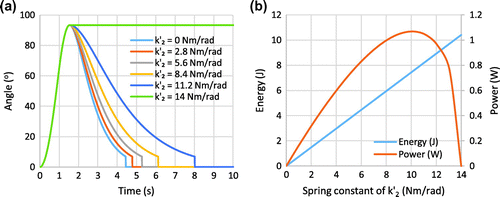
Figure 5. The utilisation factor for (a) Method 1 as a function of the damping coefficient, ξ, and (b) Method 2 as a function of k2.

Figure 5. The utilisation factor for (a) Method 1 as a function of the damping coefficient, ξ, and (b) Method 2 as a function of k′2.
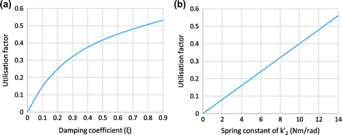
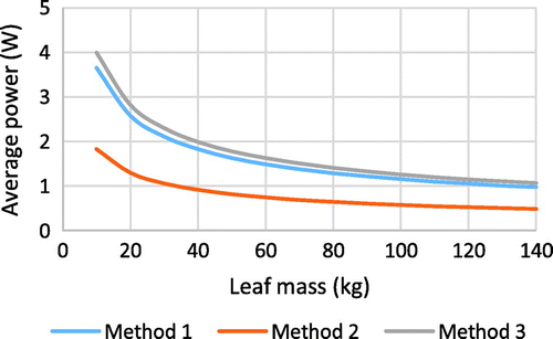
Figure 6. Average generated power for a DOE for methods 1, 2 and 3 for varying m d.

Figure 6. Average generated power for a DOE for methods 1, 2 and 3 for varying m d.

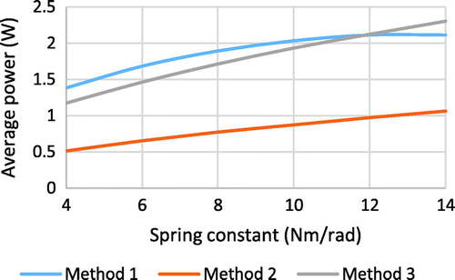
Figure 7. Average generated power for a DOE for methods 1, 2 and 3 for varying k′.

Figure 7. Average generated power for a DOE for methods 1, 2 and 3 for varying k′.

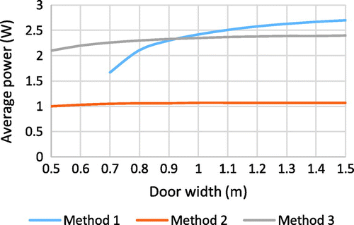
Figure 8. Average generated power for a DOE for methods 1, 2 and 3 for varying r d .

Figure 8. Average generated power for a DOE for methods 1, 2 and 3 for varying r d .

Figure 9. Diagram showing the layout of the revolving door.

Figure 9. Diagram showing the layout of the revolving door.

Table 5. Equations used to determine the motion of a revolving door

Table 6. Parameters chosen for the baseline case of the revolving door

Figure 10. Graph showing the angle of rotation and angular velocity of the revolving door as a single user passes through.
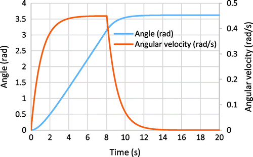
Figure 10. Graph showing the angle of rotation and angular velocity of the revolving door as a single user passes through.

Figure 11. Results for variations to the leaf mass, m L, (a) Revolving door angular rotation (solid lines) and angular velocity (dashed lines) (b) Total energy generation potential and average power output.
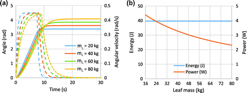
Figure 11. Results for variations to the leaf mass, m L, (a) Revolving door angular rotation (solid lines) and angular velocity (dashed lines) (b) Total energy generation potential and average power output.
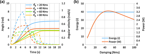
Figure 12. Results for variations to the generator damping, d g, (a) Revolving door angular rotation (solid lines) and angular velocity (dashed lines) (b) Total energy generation potential and average power output.
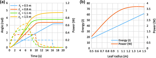
Figure 12. Results for variations to the generator damping, d g, (a) Revolving door angular rotation (solid lines) and angular velocity (dashed lines) (b) Total energy generation potential and average power output.

Figure 13. Results for variations to the leaf radius, r L, (a) Revolving door angular rotation (solid lines) and angular velocity (dashed lines) (b) Total energy generation potential and average power output.

Figure 13. Results for variations to the leaf radius, r L, (a) Revolving door angular rotation (solid lines) and angular velocity (dashed lines) (b) Total energy generation potential and average power output.

Figure 14. Continual operation of a swing door over a 1 min period, utilising generation method 3 and the baseline values for door parameters.
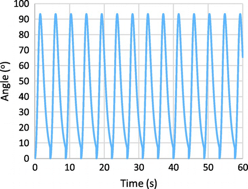
Figure 14. Continual operation of a swing door over a 1 min period, utilising generation method 3 and the baseline values for door parameters.

Figure 15. Total angular position and output power for a revolving door during continuous operation for a 60 s period.
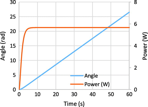
Notes: The door parameters chosen were m L = 40 kg, r L = 1.0 m and d g = 50 Nms.
Figure 15. Total angular position and output power for a revolving door during continuous operation for a 60 s period.

Table 7. Limitation to the maximum achievable generated energy using the baseline values for each of the methods of door generation