Figures & data
Figure 1. “T” equivalent circuit model of the IM: (a) in d-axis and (b) in q-axis.
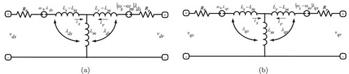
Figure 2. (a) Basic MPC control loop and (b) principle of model predictive control (MPC).
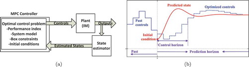
Figure 3. Block diagram of the adjustable current fed IM with NMPC.
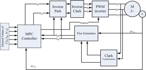
Figure 4. Block diagram of the adjustable voltage fed IM with NMPC.
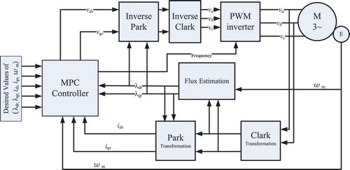
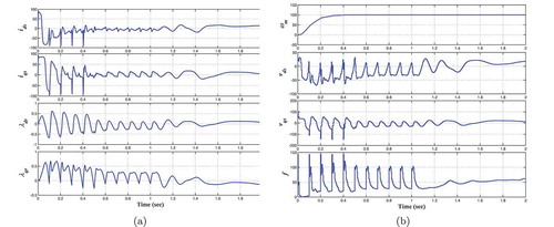
Figure 5. (a) Rotor fluxes and speed using MPC with the current-fed control method. (b) Stator currents and excitation frequency using MPC with the current-fed control method.
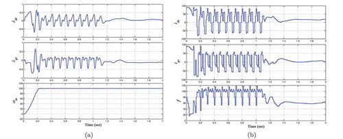
Table 1. NLP size calculation of OCP (8)
Figure 6. (a) Stator currents and rotor fluxes using MPC with the voltage-fed control method. (b) Rotor speed, stator currents and excitation frequency using MPC with the voltage-fed control method.