Figures & data
Figure 1. During single support, a residual velocity to the right will result in a fall if uncorrected for. An internal hip abduction moment (Thip) will accelerate the head, arms, trunk (HAT), and swing leg. The whole body consequentially accelerates in the opposite direction provided for by GRFh, given no slip occurs between the foot and the floor. If inertia is overcome these elements will rotate, thereby decreasing hip abduction angle. This is often inaccurately referred to as counter-rotation.
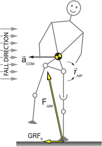
Figure 2. Possible explanation for mediolateral trunk bending as a stabilisation mechanism during prosthetic walking. For simplicity, forces, margins, and accelerations are only drawn in A. (A) Step width is increased without bending the trunk. (B) A hypothetical situation in which the entire body is rotated. (C) Lateral trunk bending including a slightly wider step, and a vertical orientation of the prosthetic leg.
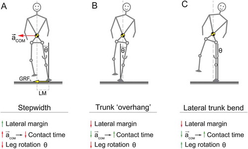
Figure 3. Frontal and sagittal view of the prototype.
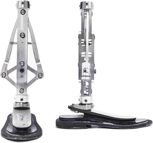
Figure 4. Mediolateral motion of the prototype. Assuming this is a right foot, a hip abduction (left image) or adduction (right image) moment will rotate and translate the femur with respect to the foot. A coupled but smaller counter-rotation (foot eversion, left image; foot inversion, right image) occurs, resulting in a combined functional change in both GRFh and CoP. Note that forces are not drawn to scale.
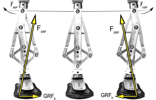
Figure 5. Location of the locking pin on the prototype. Locked, it represents a classic set-up. Participants are less aware of the intervention in this manner.

Figure 6. The set-up of the potentiometer mounted on the prototype. (A) Dorsal view of the prototype. (B) Sagittal view with the potentiometer attached to the prototype. (C) Sagittal view with the potentiometer unattached. Part 1 consists of a case for the potentiometer that can be bolted to the top bar of the prototype. Part 2 consists of a container that can be bolted to the middle bar of the prototype. The potentiometer gets inserted into the metal container of part 2. By means of a clamping screw the potentiometer can be attached frictionless. This way, the rotation angle between the top and middle bar of the prototype can be measured.
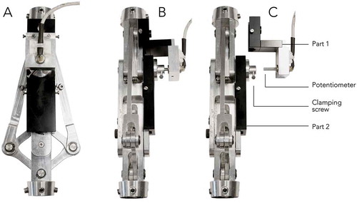
Figure 7. At terminal swing of the intended leg (here: right leg) the treadmill platform will start moving 0.05 in 750 ms. The acceleration phase lasts for 360 ms with a maximum acceleration of 0.7 m/s2, followed by a deceleration phase for 390 ms, at a maximum deceleration of 0.72 m/s2. Platform movements will be randomly to either the medial, or the lateral side.

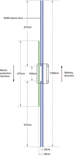
Figure 8. Top view of the beam projection layout, drawn to scale. Lengths and relative positions for the various beams are shown. Beams first appear on the VR-screen and move towards and onto the treadmill surface taking into account optical flow. Beam progression velocity is synchronised with treadmill velocity. Note the overlap (262.5 cm) between the green/striped and blue/solid beams.