
Figures & data
Figure 1. Rail car body and its suspension assembly (Zolotas & Goodall, Citation2007)
Figure 2. The free body diagram and its degree of freedom
Table 1. Input parameter for rail car system modelling
Figure 3. Design of the control of the rail car suspension system
Table 2. Zeigler-Nichols tuning rules
Figure 4. Step response of the semiactive system for 3 s (primary suspension system)
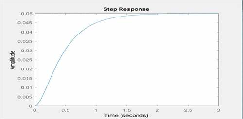
Figure 5. Adjustment of the control of the rail car suspension system
Figure 6. Adjusted step response for the active system for 3 s (primary suspension system)
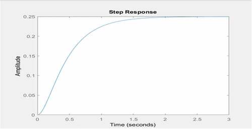
Figure 7. Oscillation response of rail car to load disturbances (primary suspension system)
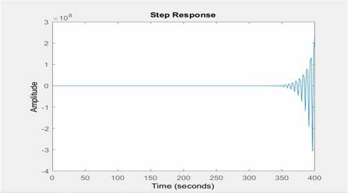
Figure 8. Response to a 0.1 m step under the PID control (primary suspension system)
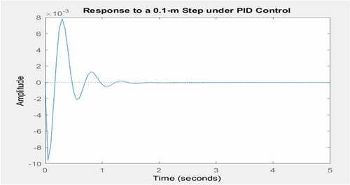
Figure 9. Response to a 0.1 m step with high gain PID (primary suspension system)
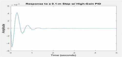
Table 3. Effects of controller parameters on closed-loop system
Figure 10. Bode diagram (primary suspension system)
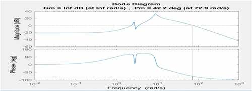
Figure 11. Oscillation response of rail car to rail disturbances (secondary suspension system)
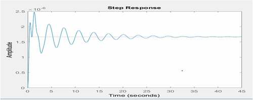
Figure 12. Response to a 0.1 m step under the PID control (secondary suspension system)
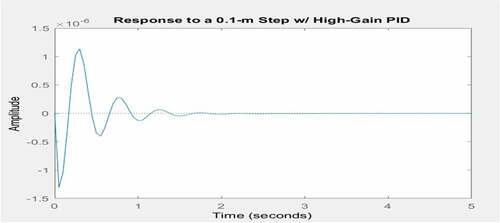
Figure 13. Final oscillation step response to rail disturbance (secondary suspension system)
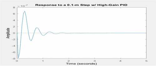
Figure 14. Bode diagram (secondary suspension system)
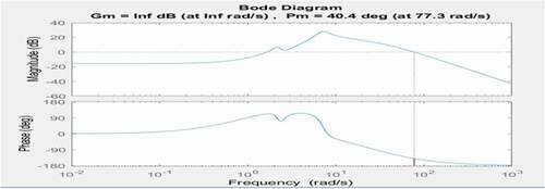
Figure 15. Vertical acceleration for the controlled and uncontrolled systems
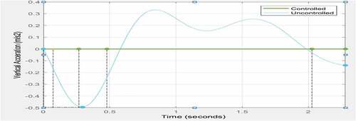
Figure 16. Pitch acceleration for the controlled and uncontrolled systems
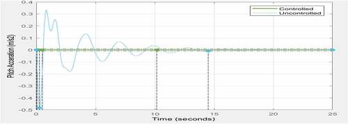
Figure 17. Output disturbance rejection
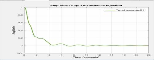
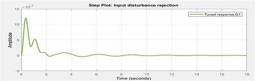
Figure 18. Input disturbance rejection
Table