Figures & data
Figure 1. Rectangular vacuum chamber manifold
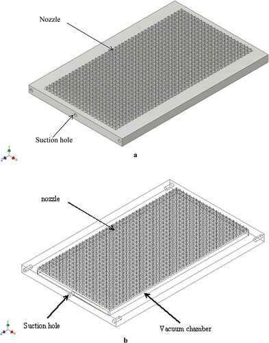
Figure 2. Cylindrical vacuum chamber type manifold
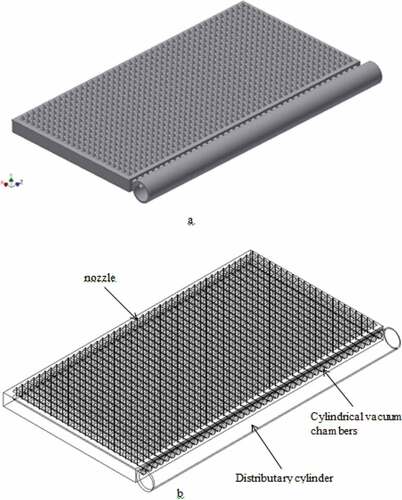
Figure 3. Simulated pressure distribution in 3 by 3 nozzle manifold
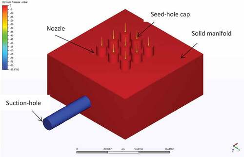
Figure 4. Simulated pressure distribution in 6 by 6 nozzle manifold
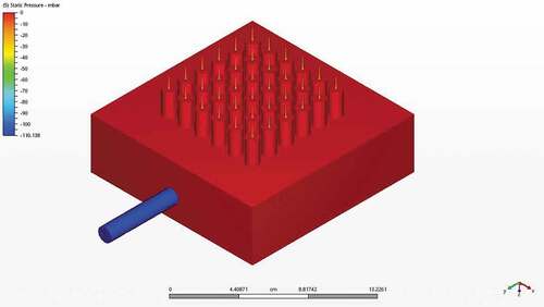
Figure 5. Simulated pressure distribution in 9 by 9 nozzle manifold
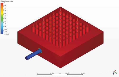
Figure 6. Four configurations of suction-outlet in 3 by 3 nozzle manifold
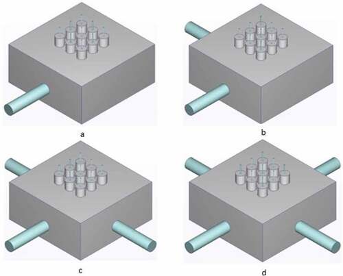
Figure 7. Four configurations of suction-outlet in 6 by 6 nozzles manifold
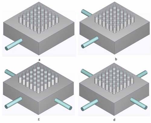
Figure 8. Four configurations of suction-outlet in 9 by 9 nozzles manifold
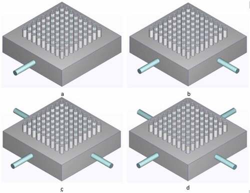
Figure 9. Simulated pressure distribution in manifold with cylindrical vacuum chamber and 924 nozzles
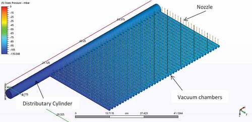
Figure 10. Zoomed manifold part showing vital features
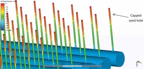
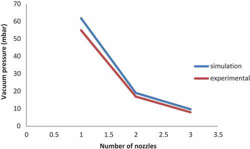
Figure 11. Experimental validation of simulated vacuum pressure distribution
Table 1. Variability parameters of pressure distribution in 3 by 3 nozzle manifold
Table 2. Variability parameters of pressure distribution in 6 by 6 nozzles manifold
Table 3. Variability parameters of pressure distribution on nozzles of 9 by 9 nozzles manifold
Figure 12. Comparison of pressure distribution between the three sizes of manifold
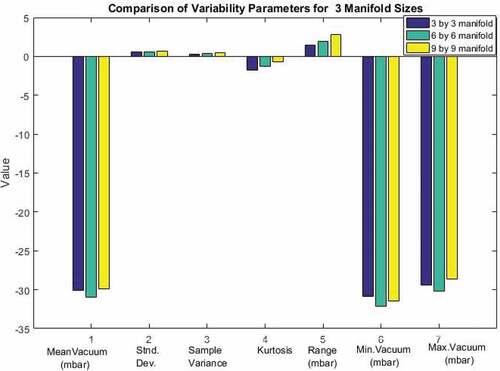
Figure 13. Comparison of pressure distribution of four outlet configurations in 3 by 3 nozzles manifold
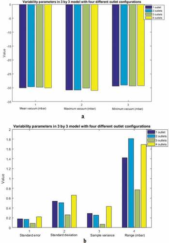
Figure 14. Comparison of pressure distribution of four outlet configurations in 6 by 6 nozzles manifold
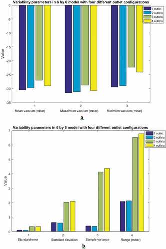
Figure 15. Graphical comparison of variability parameters in 9 by 9 nozzle manifold with four outlet configurations
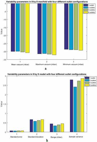
Figure 16. Pressure distribution in 924 nozzles of manifold with cylindrical vacuum chamber
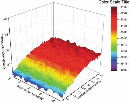
Table 4. Variability parameters among the 924 nozzles of cylindrical chamber manifold
Figure 17. Pressure distribution in 924 nozzles of manifold with rectangular vacuum chamber
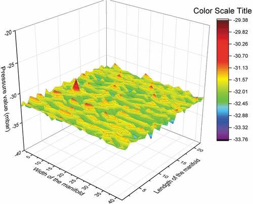
Table 5. Variability parameters among the 924 nozzles of rectangular chamber type manifold
Figure 18. Comparison of variation in vacuum pressure between cylindrical and rectangular vacuum manifolds
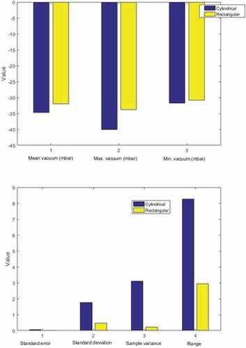
Table 6. Relationship between number of nozzles, airflow rate (cfm), and vacuum pressure (mbar)
Figure 19. Simulation and experimental pressure distribution