
Figures & data
Figure 1. (a) Engine mount assembly. (b) Original engine mount
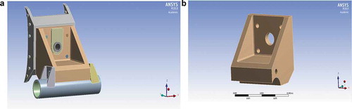
Figure 2. (a) Fixed support on mounting tabs welded to the chassis. (b) Frictionless support engine mount sitting on chassis. (c) Combined applied force from the jet engine
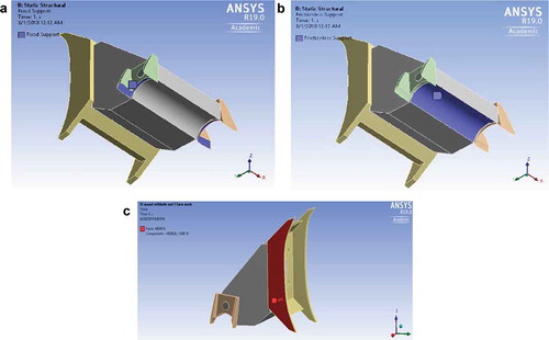
Figure 3. (a) Total deformation of assembly. (b) Total deformation of mount
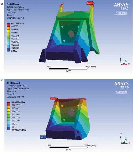
Figure 4. (a) Stress distribution in mount assembly. a-2: Stress distribution in mount assembly close-up. (b) Stress distribution in engine mount. b-2: Stress distribution in engine mount close-up
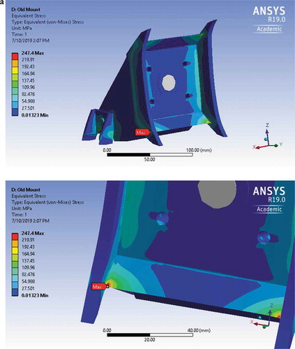
Figure 4. (Continued)
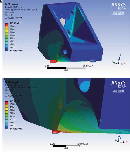
Figure 5. Structural error in engine mount
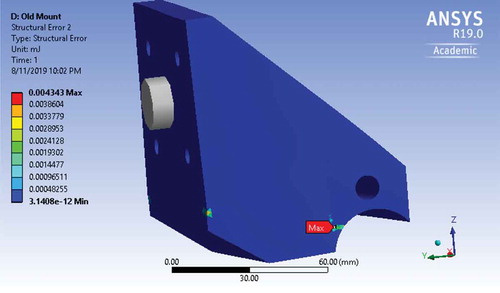
Table 1. Natural frequencies of the original mount
Figure 6. Frequency response of original mount
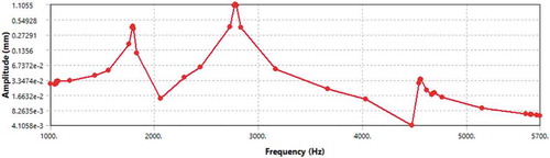
Figure 7. Total deformation of the original mount at 2775.5 Hz
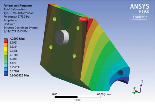
Figure 8. Initial design space
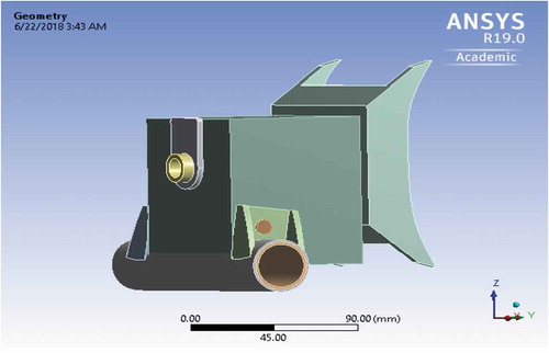
Figure 9. (a) Results of topology optimization front view. (b) Results of topology optimization top view. (c) Results of topology optimization side view
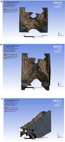
Figure 10. (a) Optimized design—front view.(b) Optimized design—isometric view
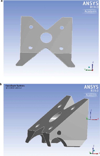
Figure 11. (a) Total deformation of assembly. (b) Total deformation of mount
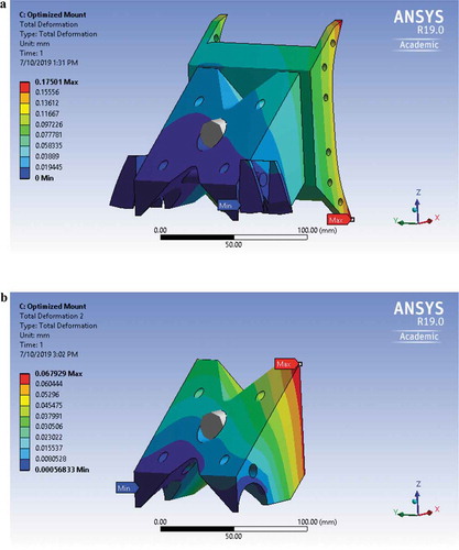
Figure 12. (a) Stress distribution in mount assembly. a-2: Stress distribution in mount assembly close-up. (b) Stress distribution in mount. b-2: Stress distribution in mount close-up
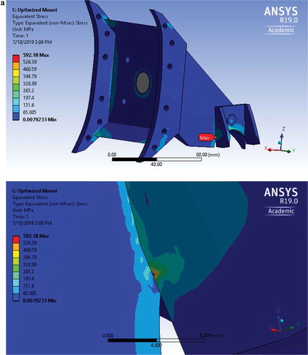
Figure 12. (Continued)
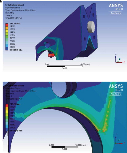
Figure 13. Structural error in engine mount
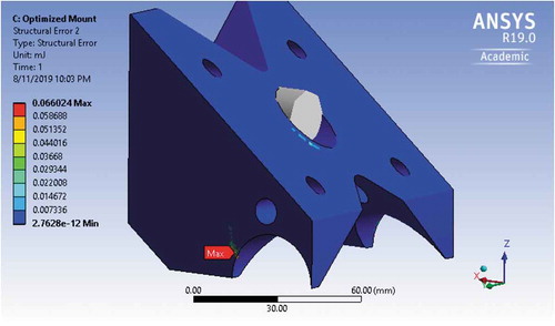
Figure 14. (a) Total deformation of assembly. (b) Total deformation of mount
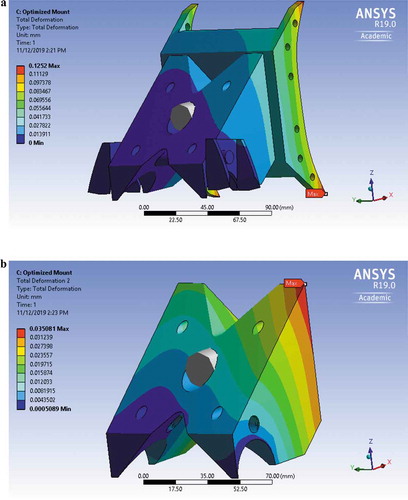
Figure 15. (a) Stress distribution in mount assembly. a-2: Stress distribution in mount assembly close-up. (b) Stress distribution in mount
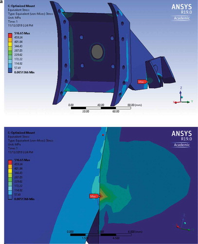
Figure 15. (Continued)
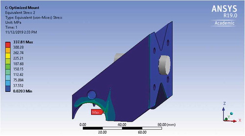
Figure 16. Structural error in engine mount
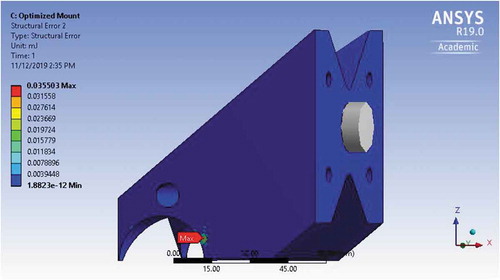
Table 2. Frequency range of optimized mounts
Figure 17. Frequency response of optimized mount
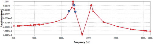
Figure 18. Total deformation of the redesigned mount at 2416.4 Hz
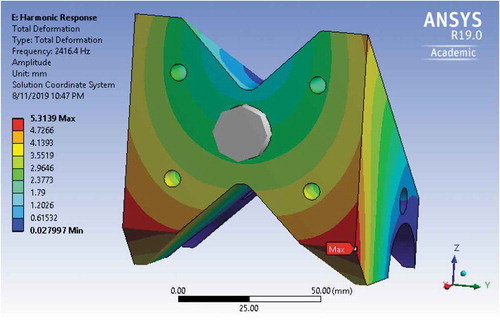
Figure 19. Frequency response of optimized mount
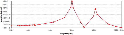
Figure 20. Total deformation of the redesigned mount at 2996.6 Hz
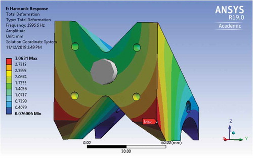
Table 3. Results summary
Figure 21. Factor of safety for aluminum optimized mount
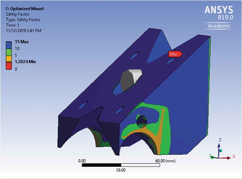
Figure 22. Factor of safety for structural steel optimized mount
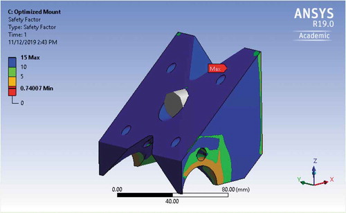
Table 4. Price difference between original and aluminum optimized mount
Table 5. Price difference between original and optimized mount