Figures & data
Figure 1. Modified gear-based knee joint prosthesis with the integrated locking mechanism, (a) CAD design and (b) real view
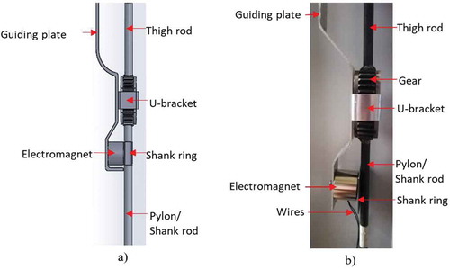
Figure 2. Block diagram of the locking mechanism
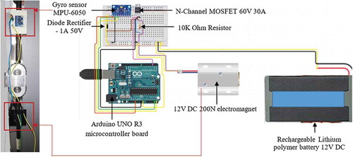
Figure 3. Illustration of wiring of the control circuit
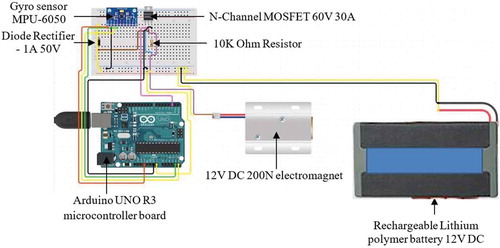
Figure 4. Set-up of the experiment
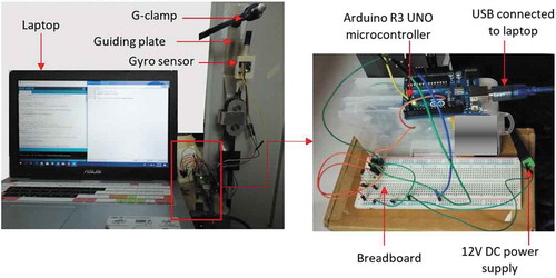
Figure 5. Procedure of experiment
Figure 6. Algorithm of the program code
Figure 7. The state of locking mechanism with the fluctuation of y, p and r values during normal speed walking
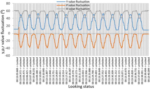
Figure 8. The fluctuation of y, p and r values during a sudden disturbance
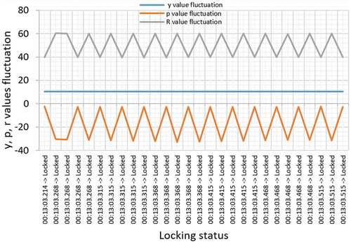
Figure 9. Knee joint at (a) locked state, (b) transition from locked to unlocked state, (c) corresponding data from the controller
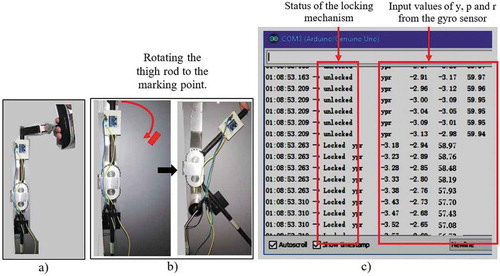
Figure 10. Knee joint at (a) locked condition (b) unlocked condition
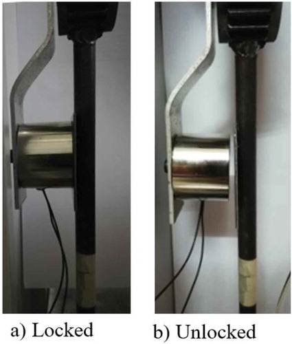
Figure 11. Fluctuation of “p” and “r” values when the locking mechanism triggered from unlocked to locked state and vice-versa
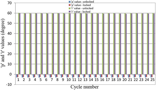
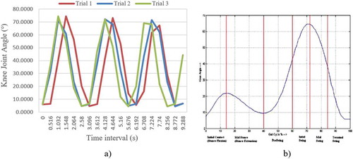
Figure 12. Angle of knee joint at different points of time during the gait cycle (a) experimental data, (b) real gait cycle (Nandy et al., Citation2012)