Figures & data
Figure 1. Effect of volume ratio on the clear distance between the OFs of different diameters
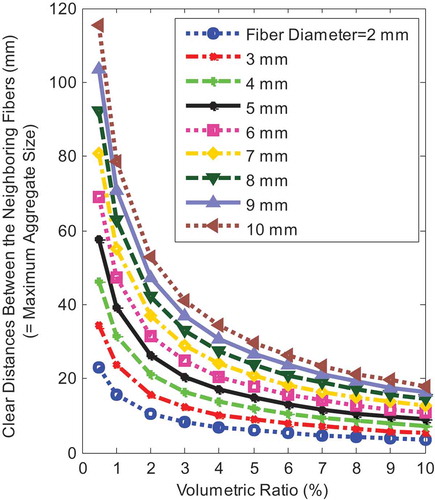
Figure 2. Formwork and construction of the TCP
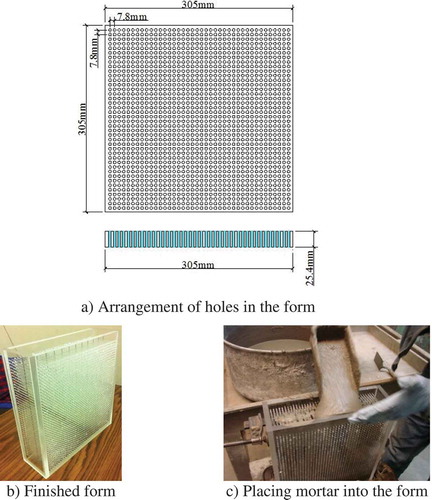
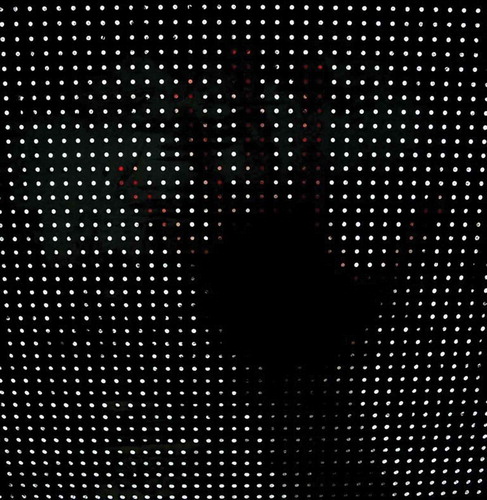
Figure 3. Finished TCP
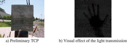
Figure 4. Light transmission in graded-index single mode fiber [14]
![Figure 4. Light transmission in graded-index single mode fiber [14]](/cms/asset/f129681c-33d5-49a3-94f7-214d50984ab4/oaen_a_1756145_f0004_oc.jpg)
Figure 5. Light transmission in the step index fiber
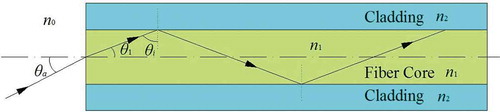
Table 1. Properties of the optical fibers
Figure 6. Light transmission simulation of a single fiber
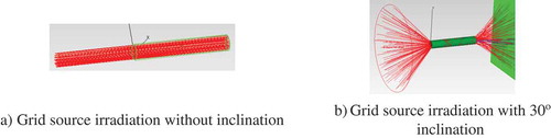
Figure 7. Variation of light transmission efficiency with incidence angle
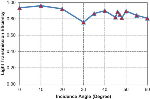
Figure 8. Mechanical stress analysis of bent OF
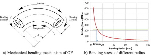
Figure 9. Optical analysis of the bending
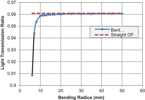
Figure 10. Test setup for light irradiation tests
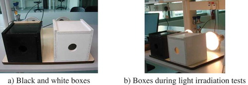
Table 2. Volume ratio of wood panels in place of the TCPs for convenience
Figure 11. Experimental results of irradiation tests of TCPs
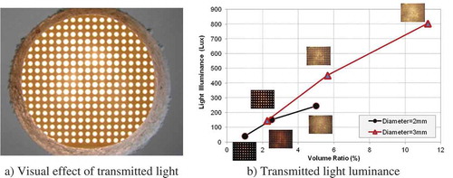
Figure 12. Numerical model of the irradiation test
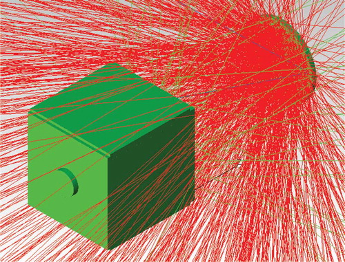
Figure 13. Comparison of light irradiation results and source of difference between experimental and numerical values
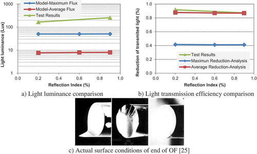
Figure 14. CPC with edge-ray principle
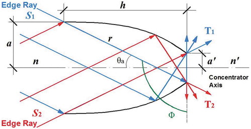
Figure 15. CPC total length variation with the half-acceptance angle for different exit aperture diameter
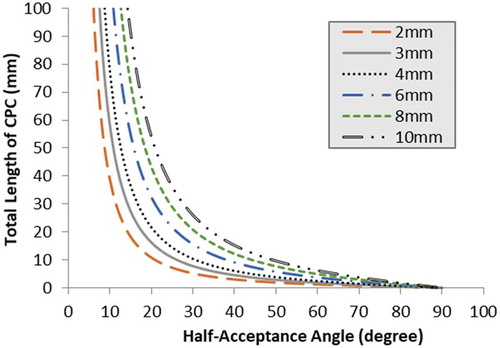
Figure 16. Concentration ratio of CPC
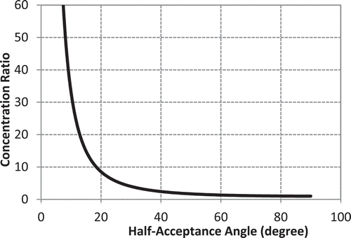
Figure 17. CPC with different geometry
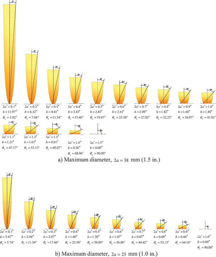
Figure 18. CPC and OF computational model
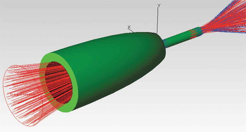
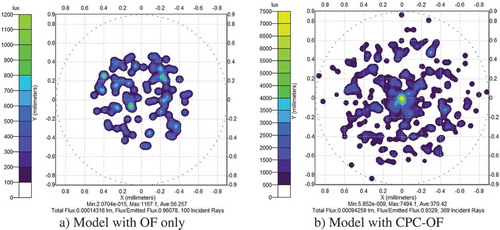
Figure 19. Illuminance maps at the exit cross-section of the OF from simulations